A user-defined shape for open channels in an InfoWorks network is defined by a set of height-width relationships. Vertically symmetric or vertically asymmetric cross sections can be defined.
The shape can either be defined by specifying factors to define a normalised shape or by entering surveyed dimensions as a non-normalised shape.
When defining a normalised shape, factors between 0 and 1 are used to define the set of height-width relationships. To calculate the actual cross section of the open channel that the shape is associated with, InfoWorks WS Pro multiplies the shape profile by the values in the cross section height and width fields of the associated open channel.
When defining a non-normalised shape, actual height-width values can be entered.
For asymmetric shapes, width at a corresponding height is defined by entering Left hand side and Right hand side values, where Left hand side represents the position of the left-hand side of the cross-section and Right hand side represents the position of the right-hand side of the cross-section. When defining a normalised shape, the range for both is 0 (far left) to 1 (far right).
Specifying a user-defined shape
To define a new user-defined shape
- In the
Open channel property sheet, click the Shape ID arrow (
 ) and select Insert New Shape Object option from the context menu.
- Enter a name for the new shape and click OK. This displays the Shape Property Sheet.
Note: Alternatively, you can input a name in the Shape ID property and select Create Shape from the Shape ID arrow () to create a new Shape ID.
- Choose a Shape type of either Symmetric or Asymmetric. Click OK.
- Enter a Description (optional).
- Click the Geometry field button to display the Shape Geometry Editor.
- By default, the Normalised option is checked. With this option checked, factors between 0 and 1 are entered in the geometry editor to define a normalised shape. Uncheck the Normalised option to enter actual height and width values in the editor.
- In the Geometry Editor, specify a series of Height and Width relationships for the shape (see below for examples of defining normalised shapes). Height values must be entered in ascending order and must be unique, therefore it is necessary to specify slightly different height values if two points are required at the same height. The new shape is illustrated in the editor as the relationships are entered.
- Click OK when the shape has been defined.
Alternatively, a new shape can be added in the append row of the Shape Grid Window of the Links Grid. Double-click the new shape to display the Shape property sheet.
Defining normalised shapes
There are a few important rules to consider when working with normalised user-defined shapes:
- Factors are used when constructing the normalised user-defined shape. The maximum height needs to be made equal to 1 and the maximum width needs to be made equal to 1. Any other height or width has to be re-calculated as a function of these maxima.
- The Height must be a value between 0 and 1. The Width must be between 0 and 1. Heights and widths can be entered up to six decimal places.
- Heights have to be entered in the software in ascending order with the last value being 1. This is why it is recommended to work your way up height values, starting at 0 and finishing at 1. If the first height is non-zero then it is assumed that the width is zero at height zero and that the position of the right-hand side and left-hand side is 0.5 (that is, the base of the shape is at the central point).
- Heights must be unique values so if you need to enter two points at the same height, the values must differ by at least 0.000010.
- Once the characteristics of the user-defined shape have been specified in factors, the user is required to enter the real values in the Width and Height boxes in the Shape frame of the Open channel property sheet. (The shape is "stretched" to fit these values).
- For an enclosed shape (as opposed to an open shape):
- The width must be zero at height 1 for a symmetric shape, otherwise it is assumed that the shape is for an open channel.
- Left and right should be equal to each other at height 1 for an asymmetric shape; otherwise, it is assumed that the shape is for an open channel.
Examples
The examples below show how to enter geometry data for a normalised symmetric and asymmetric cross section.
(To enter actual cross section dimensions, uncheck the Normalised option on the Shape geometry editor. When a non-normalised shape is associated with a open channel, the shape geometry will not be multiplied by the open channel cross section height and width values.)
Symmetric Shape
0.15m wide at the base 0.4m wide at the top and 0.6m high (enclosed sewer).
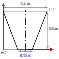
The largest height is 0.6 m, therefore it gets given a value of 1.
The largest width is 0.4 m therefore it gets given a value of 1.
The base width of 0.15 becomes 0.15/0.4 (0.375) in the new factored system.
The Shape Geometry Editor should look like this:
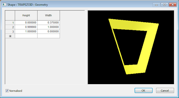
- Start at height = 0. At height = 0, width is 0.15 m, which corresponds to a factor of 0.15/0.4 = 0.375
- Next height is height = 1. At this height, width is at its maximum (0.4 m), so it gets given a factor of 1
- Because we have a symmetric shape that is enclosed, we must specify a width of 0 at height = 1.
- As we cannot have two lines with the same height, a value of 0.999990 or 0.999900 must be entered instead in the middle row.
Click OK on the editor above.
In Open channel property sheet, enter 400 mm in the Width box and 600 mm in the Height box. It is important to enter the real values, not the factored values.
Asymmetric Shape
Asymmetric shape as shown in the picture below:
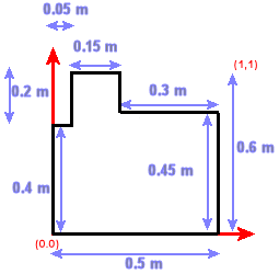
The largest height is 0.6 m, therefore it gets given a value of 1.
The largest width is 0.5 m therefore it gets given a value of 1.
The other heights and widths should be calculated as functions of the maximum values, e.g. width of 0.05 m at 0.4 m height becomes 0.05/0.5 = 0.1.
The Shape Geometry Editor should look like this:
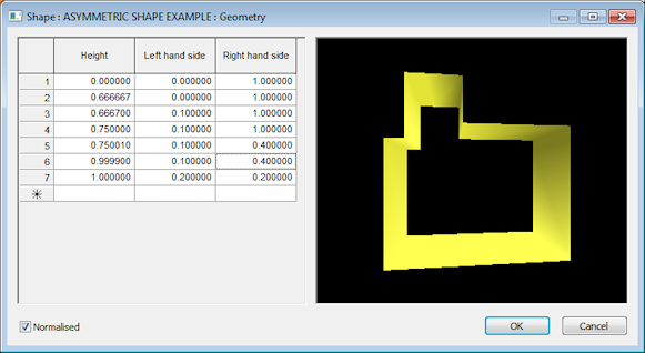
For an asymmetric shape, it may be useful to project the geometry on the Y axis (height) to work out which points will be needed to build the shape in the software, and what their coordinates will be. Left and Right values are attributed according to the projection of the point on the far left and far right sides.
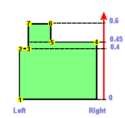
- Start at height = 0 (Point 1). At height = 0 the width is at its maximum, therefore Left = 0 (far left) and Right = 1 (far right)
- The next height is 0.4 m which corresponds to a factor of 0.666667 (factor of 0.4/0.6). This is Point 2 in the image above. At this point, the width is still at its maximum therefore Left = 0 (far left) and Right = 1 (far right)
- The next point up is Point 3. Its height is the same as Point 2's so we are going to give it a height of 0.666700 (values must differ by at least 0.000010). Left = 0.1(= 0.05/0.5) and Right = 1 (far right).
- The next point up is Point 4. Its height is 0.45 m, or 0.45/0.6 = 0.75. Left = 0.1 (0.05/0.5) and Right = 1 (far right).
- The next point up is Point 5. Its height is the same as the one for point 4 so we are going to allocate it a height of 0.750010. Left = 0.1 (0.05/0.5) and Right = 0.4 (0.2/0.5).
- Next point is Point 6. Point 6 height is 0.6, therefore a factor of 1 (because of the next bullet point, we will enter a value of 0.999900 instead). Left and Right are the same as for Point 5 : Left = 0.1 (0.05/0.5) and Right = 0.4 (0.2/0.5).
- Finally as the shape is enclosed, we need to add a final line at height = 1, for which Left and Right are equal to one another. Any factor between 0.1 (0.05/0.1) and 0.4 (0.2/0.5) can be chosen. Left = Right = 0.2.
Click OK on the Shape Geometry Editor.
In the Open channel property sheet, enter 500 mm in the Width box and 600 mm in the Height box. It is important to enter the real values, not the factored values.