- Modifying the grid spacing
- Resizing and moving the grid
- Rotating the grid
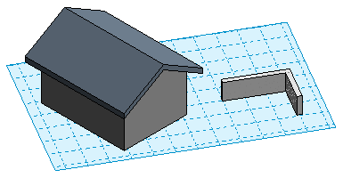
When using a work plane, you can modify its grid by:
To modify the work plane grid
- If necessary, click Model tab
 Work Plane panel
 (Show), to display the work plane.
 - Select the work plane. Note: Click the edge of the work plane to select it.
- Do any of the following:
- Modify the grid spacing: On the Options Bar, for Spacing, enter a value to specify the desired distance between grid lines.
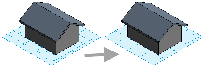
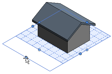
- Resize and move the grid: To move the grid, drag a grid edge. To resize the grid, drag the grips.
- Rotate the grid: Click Modify | Work Plane Grid tabModify panel
 (Rotate), and rotate the grid. For full instructions, see Rotating Elements.
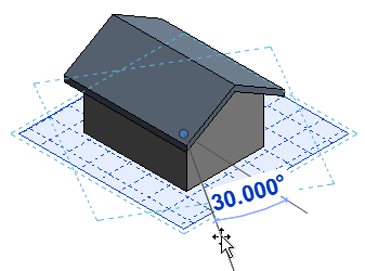
- Modify the grid spacing: On the Options Bar, for Spacing, enter a value to specify the desired distance between grid lines.
About rotating the grid
When you rotate a work plane grid, the new orientation affects placement of components and affects the rectangle draw option for walls and lines. For example, if you rotate the work plane grid and then place a component, the component is oriented on the same angle as the work plane grid. If you create a chain of walls with the rectangle option, you can create them in the orientation of the work plane grid only.