Divide paths and form edges to define the nodes on which components are placed.
When you divide a path, nodes are applied to denote the position of the points of placement for components. The division is done by means of determining a number of divisions, distance between divisions, or by intersection with references (levels, vertical reference planes, or other divided paths).
- In the drawing area, sketch a model or reference line on which repeated adaptive components will be placed.
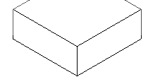
Similarly, a form can be created and any of its edges can be used.
Model Line Form Edge 
- In the drawing area select the path to be divided. If the path is a form edge, press the Ctrl key to select both sides of a circle, or each side of a polygon.
- Click Modify | Lines tab
 Divide panel
  Divide Path.
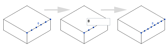
Divided Model Line Divided Form Edge 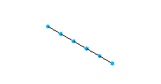

By default the path divides into 5 segments with 6 equidistant nodes (Imperial templates) or 4 segments with 5 equidistant nodes (metric templates). You can modify the number and spacing of nodes if necessary.
In the drawing area, the number of nodes displays for the divided path. Click this number and enter a new number of nodes. Press Enter when finished to change the divisions.
Similarly, select a divided path and adjust its Number property under the Node section of the Properties palette. This may require changing the Layout property to Fixed Number if the layout method has been changed.
You adjust the spacing layout by modifying the properties of the divided path.
You can also tab select a divided path to divide it additional times.