Creating Grading Pads
Learn the benefits of grading pads and zone interaction.
Learning Objectives
- Create nested and overlapped zones.
- Working with slope constraints of higher-positioned zones in the Grading Object Browser override those of zones beneath.
- Use a grading pad zone to relax slopes along the grading limit.
- Use a hinge zone to adjust how much the solver will raise the grading pad.
In Analysing the Convergence Plot and Violations you discovered that close to the southern grading limit boundary, Grading Optimization is not able to incline the triangles at the specified minimum 1% towards the drain line in the river. The problem is that the grading limit is fixed and the profile of this fixed grading limit makes a 1% slope impossible in the given direction. The slope constraint must be further relaxed.
Adjust Slope Settings in the Grading Limit
In the Grading Objects Browser, select the grading limit under the Grading Limit category.

In the Grading Limit Properties panel:
- Select Customise slope constraints.
- Specify Max slope to 33%.
- Specify Min drain slope back to 0%.
Close Grading Optimization.
Create a Nested Zone
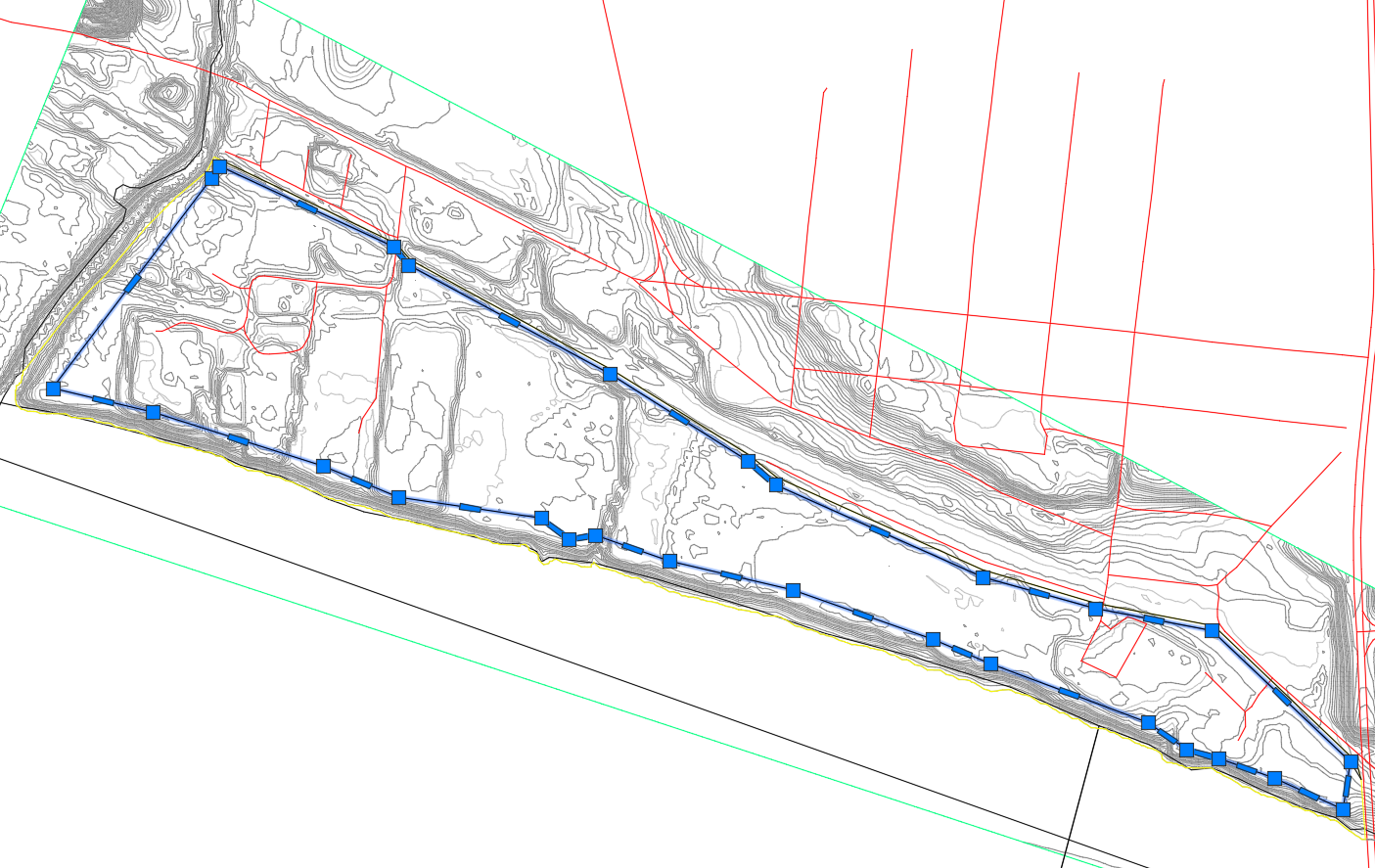
You still need the main drain pattern to slope towards the river. Because the triangles along the grading limit border should not be constrained with the minimum drain slope, a second nested zone inside the grading limit needs to be created. This grading pad gives the areas between the grading limit boundary and the grading pad enough freedom to compensate for the difficult profile determined in the previous exercise.
In Civil 3D, select the black polygon that is inside the yellow Grading Limit polygon.
In the Grading Object Tools Palette, select
 Zone.
Zone.Press Enter.
In the Zone Properties panel:
Rename the zone Grading Pad.
Select Customise slope constraints.
Specify Max slope to 5%.
Specify Min drain slope to 1%
Note: Remember that the general existing ground slope is less than 2%.
Click Analyse tab > Grading Optimization panel >
 Optimise to open Grading Optimization.
Notice in the Grading Object Browser that the new zone has been created.

Zone Order and Constraint Overrides
When working with multiple zones that overlap, the order of the zones in the tree view affects the priority of the constraints.
With overlapping zones, the slope constraints of zones above other zones override the slope constraints of zones underneath.
This is an important relationship to understand and is illustrated in the following image.
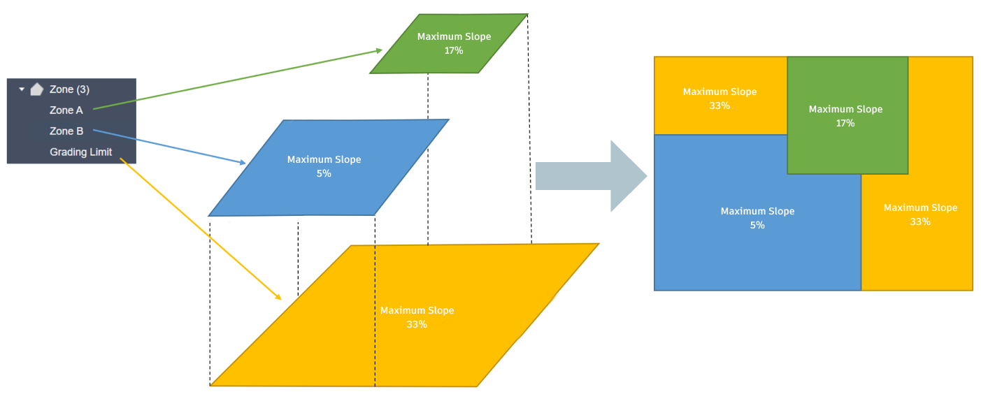
- The Grading Limit (orange) and is at the bottom with a max slope of 33%.
- Zone B (blue) is above the grading limit with a max slope of 5%.
- Zone A (green) is above Zone B with a max slope of 17%.
The image to the right in this conceptual image shows how the slope settings on the surface will be prioritised in this scenario.
In the Grading Object Browser, you can drag and drop zones to be reordered in the tree view.
Zones can only be ordered in the tree view inside Grading Optimization. The tree view inside Civil 3D does not support this ordering.
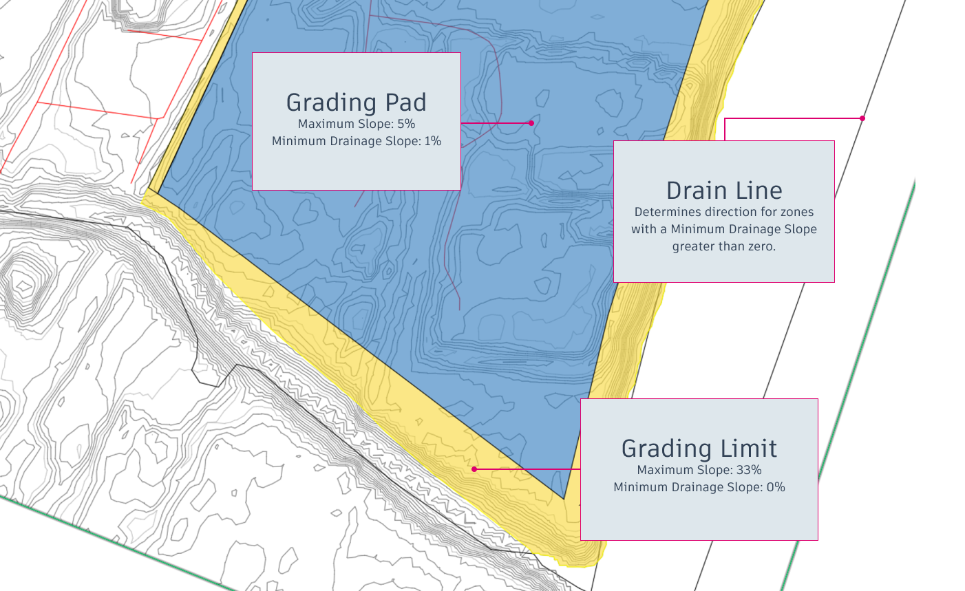
In the following illustration you can see the yellow grading limit at the bottom, which is overridden by the slope constraints of the grading pad above it.
Adjust Optimisation Settings and Optimise
- On the Optimisation Toolbar, click
 Optimisation Options.
 - Raise the objective weights to 100.
- Decrease the iterations to 25,000.
- Click
 Optimise to run the optimisation again.
 - Click
 on either the Violation tab or Cut-fill tab of the Optimisation Panel.
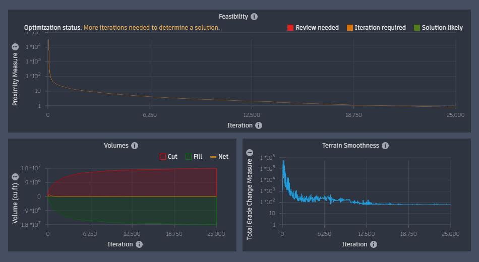
Observe that the proximity value descends to a feasible solution. Spikes in the second half of the optimisation are a good sign that shows the solver is finding its way towards a solution, as long as the overall direction trends downwards.
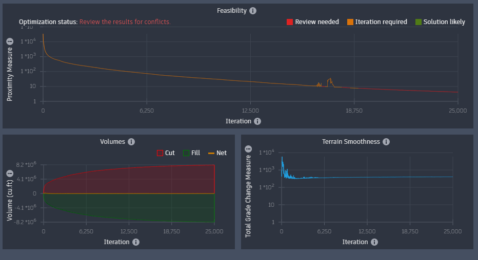
The cut and fill volumes do grow as the feasibility improves. The solver is cutting and filling more in order to satisfy all the slope constraints.
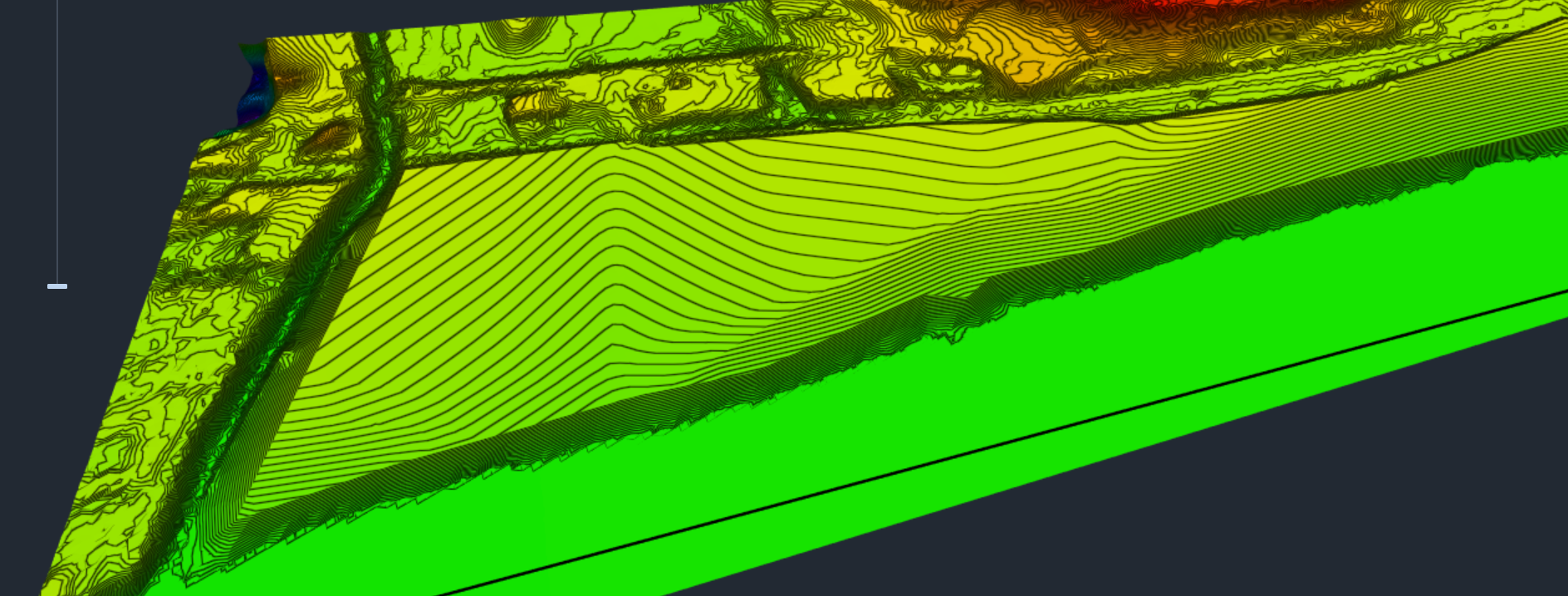
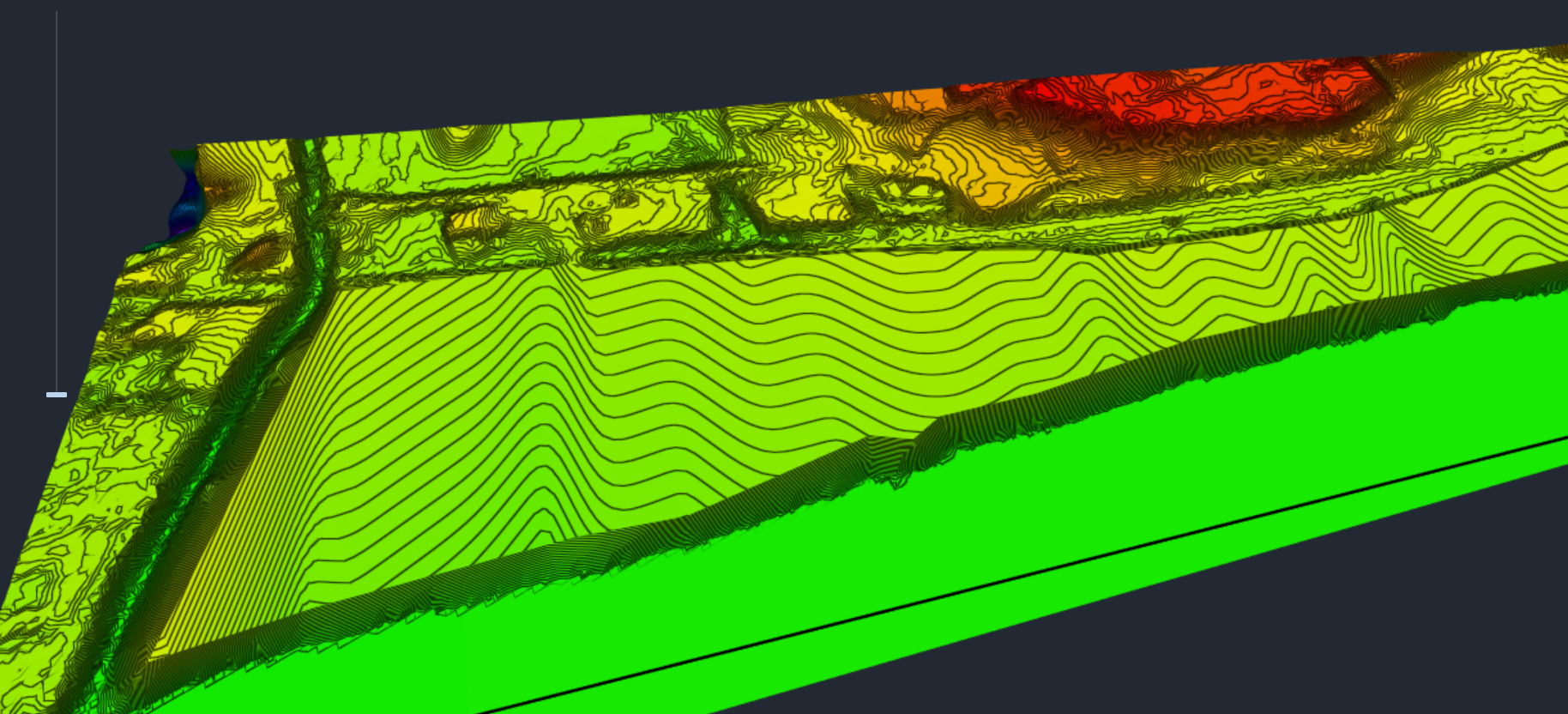
Though this is a much better solution than previous surface grading attempts, closer analysis shows potential improvements are possible. There is a steep fill slope at the allowed 33% at the back of the grading limit, sloping up towards the grading pad. This was created for two reasons:
- The pad lifted in the back to slope towards the river for drainage.
- Cut and fill balance.

When mass-grading a site like this, you generally don't want such a steep fill slope at the property boundary. It can be fixed by placing a hinge zone.
Create a Hinge Zone
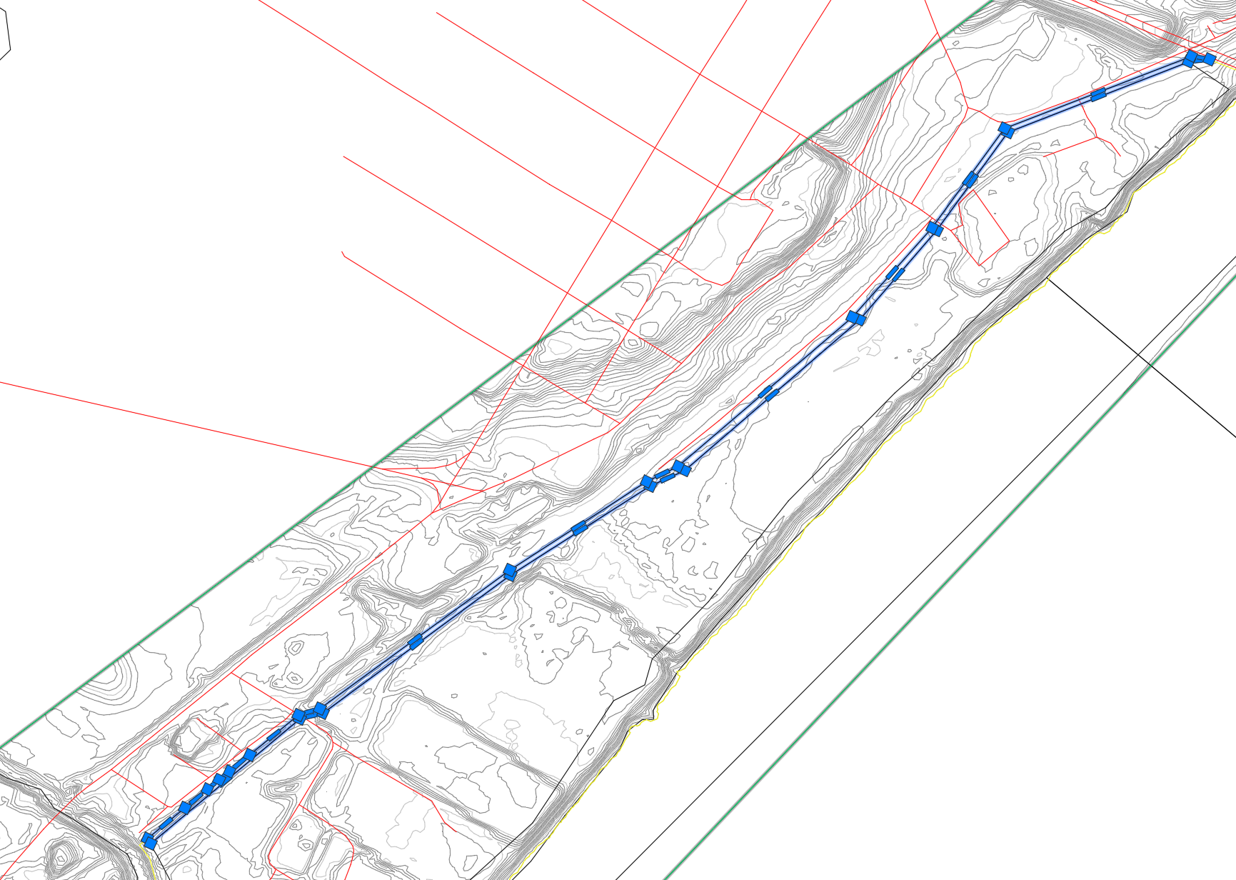
By creating a narrow zone between the grading limit border and the grading pad, a connection is made between the two with a maximum slope setting of less than 33%. This hinge zone will prevent the steep fill slope.
We select the narrow polygon at the east boundary of the property and assign a zone to it.
In Civil 3D, select the black polygon that is inside the yellow Grading Limit polygon.
In the Grading Object Tools Palette, select
 Zone.
Zone.Press Enter.
In the Zone Properties panel:
Rename the zone Hinge Zone.
Select Customise slope constraints.
Specify Max slope to 10%.
Specify Min drain slope to 0%.
Note: The Minimum drainage slope is set to 0 because it should not slope towards the river.
Click Analyse tab > Grading Optimization panel >
 Optimise to open Grading Optimization.
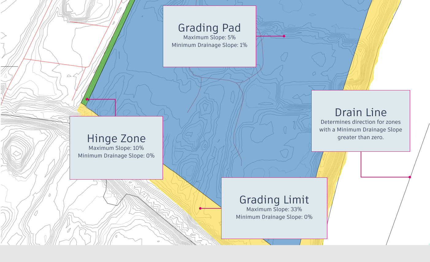
In the following illustration, you can see the yellow grading limit at the bottom, which is overridden by the slope constraints of the grading pad above it. The hinge zone fills the space between the northern edge of the grading limit and the grading pad.
Run the Optimisation
- Click
 Optimise to run the optimisation again.
 - Click
 on either the Violation tab or Cut-fill tab of the Optimisation Panel.
Watch the downward trend of the proximity value and the stable cut and fill volumes.
The surface still has small mounds on top of the benching.

This is likely because it cannot grade the benching steeper than 33% and the hinge zone prevents optimisation from further lifting the grading pad. A final step will likely produce a surface meeting your requirements.
Fine Tune the Grading
In the Grading Objects Browser, select Hinge Zone under the Zone category.
In the Grading Limit Properties panel:
Select Customise slope constraints.
Specify Max slope to 15%.
Note: This allows Grading Optimization to lift the grading pad slightly higher in the back, sufficiently removing the mounds in front.
Click
 Optimise to run the optimisation again.
Click
 on either the Violation tab or Cut-fill tab of the Optimisation Panel.
Again, notice the downward trend for the feasibility plot and stable volumes.
The final mass-graded surface with the cleaned-up benching is complete.
