The following features are common to all materials:
Roughness Specific Parameters
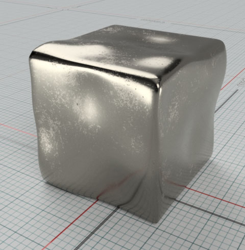
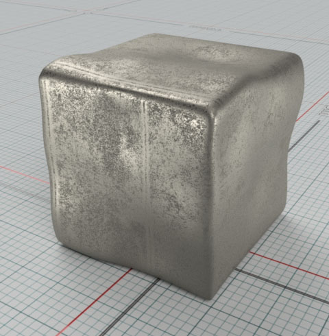
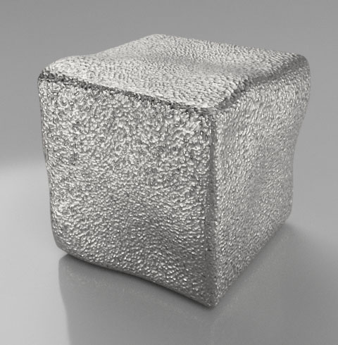
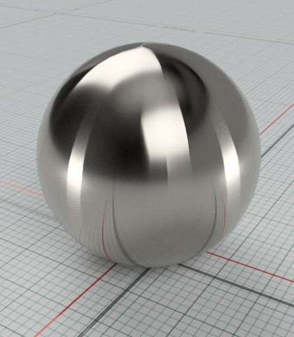
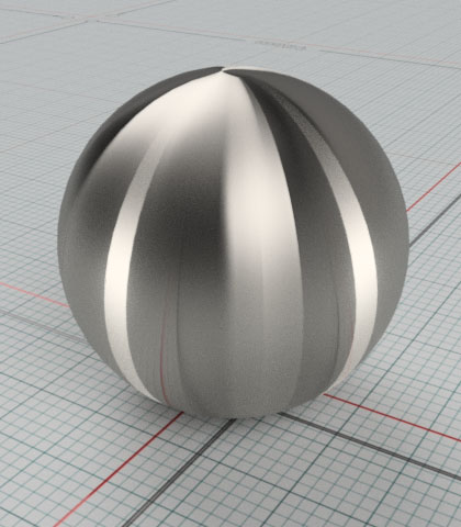
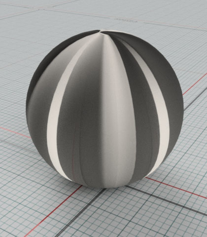
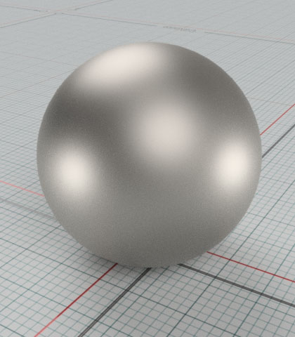
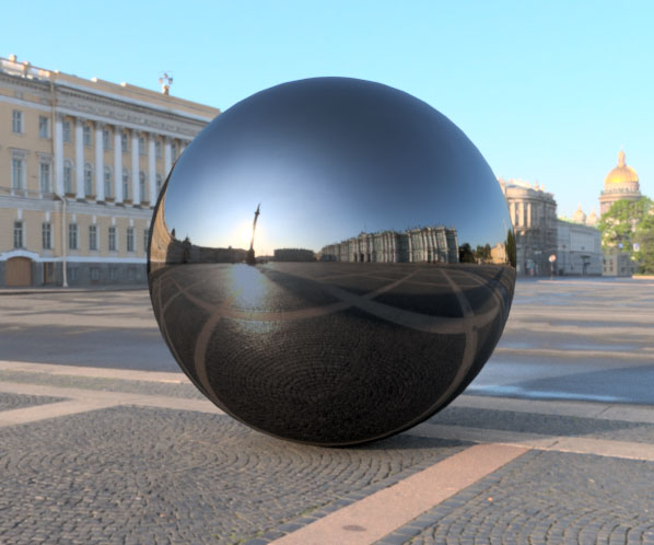
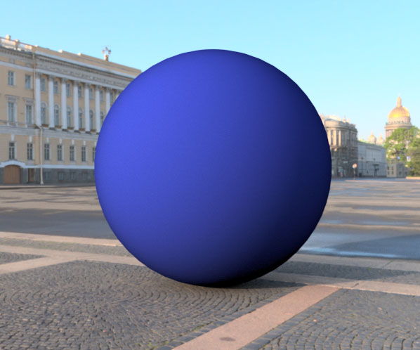
Roughness is a consequence of irregularities on the surface. A polished surface will have very few of them, resulting in a mirror-like reflection, while a rough, unfinished or finished to satin or matte, will reflect light on a wide spread.
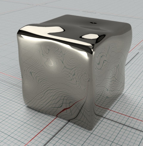 Polished (mirror) |
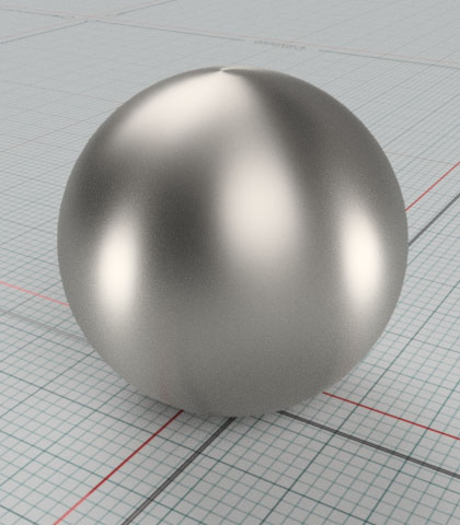
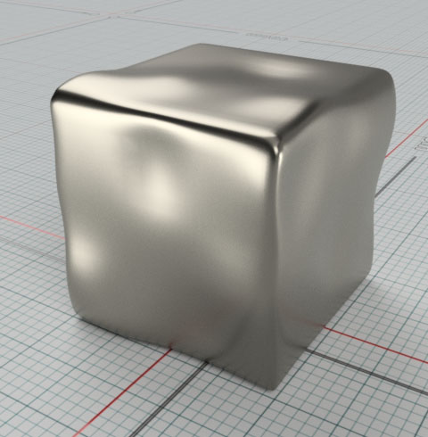 Satin |
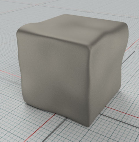 Matte |
You can use a uniform value for a uniform finish, or a texture for a variable roughness resembling an unfinished or organic surface.
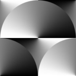
For a texture, black pixels will represent mirror-like finish, and white pixels a matte finish. Gray pixels represent all the in-between finishes.
 Texture example 1 |
 Texture example 2 |
- Roughness
- The amount of Roughness (0.0 to 1.0) or the texture to be used to control the amount (black = 0.0, white = 1.0)
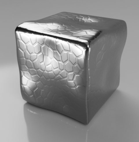
Bump/Normal Maps Specific Parameters
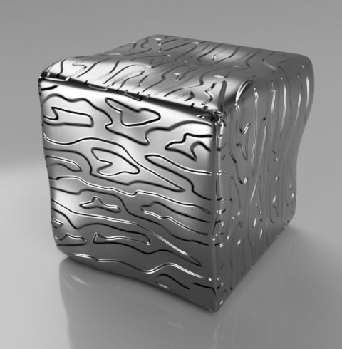
Often surfaces are textured with specific patterns or are bumpy due to manufacturing or natural processes. If these bumps are not raising too much from the surface they do not need to be modeled and can instead be approximated efficiently by a texture.
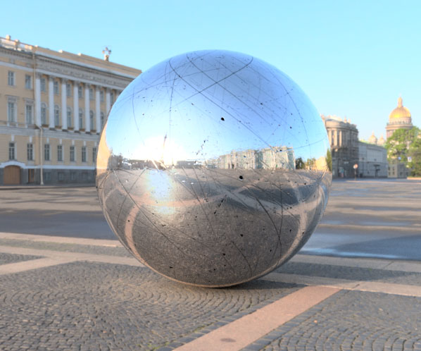
Examples are irregularities from a metal cast, patterns in injection molding, or scratches
 Cast iron |
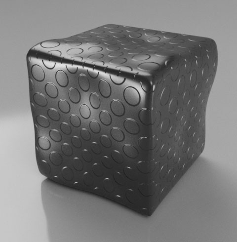 Injection molding |
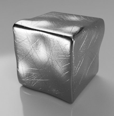 Scratches |
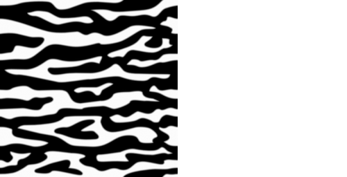
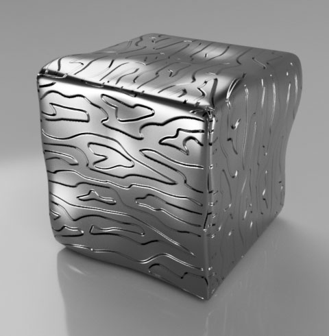
- Image
- The texture to be used to control the bump. It can be a height map (greyscale image) or a normal map.
-
Height map
Normal map
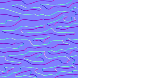
- A height map uses grey/white pixels to show how much that area is raised from the black base surface. The actual amount need to be specified by some other value. See Depth Amount below.
- Normal maps instead use the Red and Green channels of a pixel to calculate the orientation of the surface at that point. The direction is an absolute value that guarantees an accurate representation of the original surface.
- Depth Amount
- For Height maps specifies the height of the white pixels in physical units.
- For Normal maps acts as a multiplier to increase or decrease the normal map direction values.
-

Increasing amounts of depth using the same bump texture
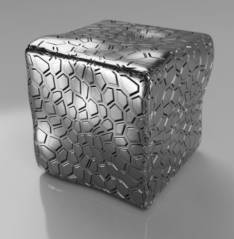
Cutout
A cutout texture is used to create holes in a surface. A cutout does make the material invisible where the texture is black, and fully visible where white.
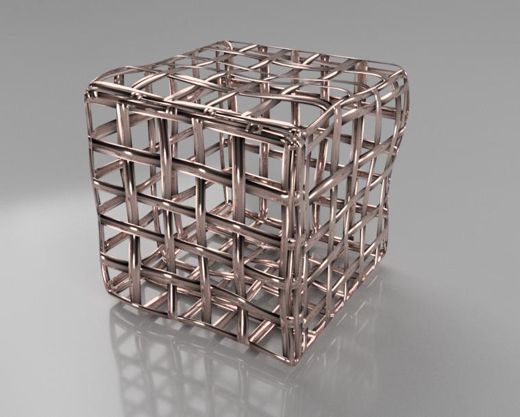
Cutout does not make a material “transparent” as a transparent material still reflects and refracts.
A cutout surface also does not extrude or fix the cut volume in any way. It’s purely a surface effect, so it’s best suited for thin objects like wire meshes or laser cut panels.
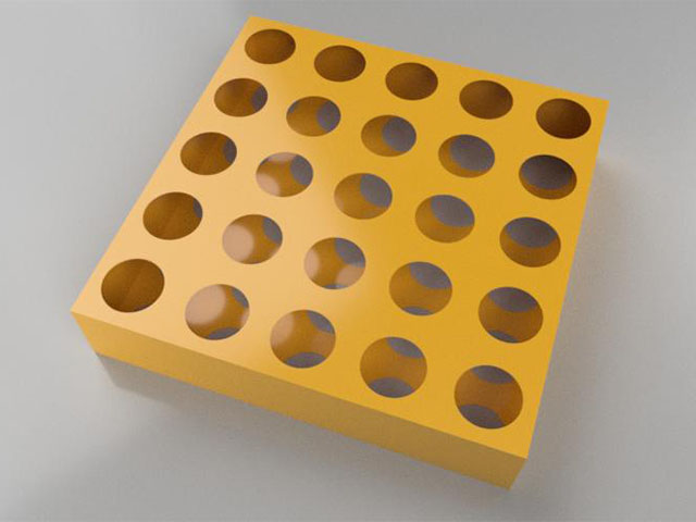 Cutouts on a thick object |
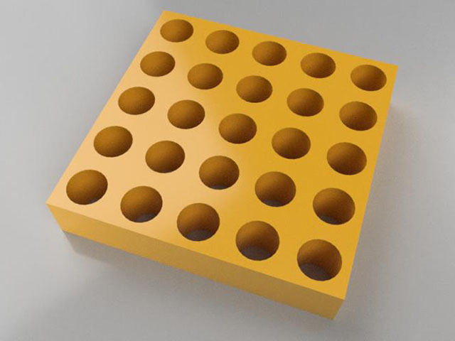 Real holes |
As textures are based on UV coordinates, surfaces on both side of a thin object need to be aligned for the holes pattern to be aligned too.
Grayscale values in the texture are supported mainly to provide aliasing to the edges between black and white areas of the texture.
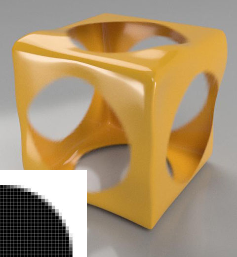 |
 |
In the above exaggerated scale example, you can see how support for grayscale in the cutout texture helps smoothing edges where the texture resolution is noticeable.
Because of the specific use, Cutout can only use textures and not solid colors. It is possible to use a uniformly grey texture to partially fade an otherwise solid material to show something behind for illustration purposes. Just keep in mind that the result is not physically possible and might not work as expected in some cases.
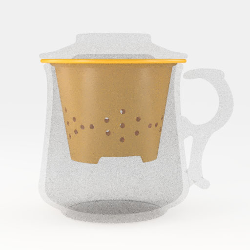 Grey cutout texture |
 Transparent material |
Above you can see how using a grey cutout texture isolate part from an object in a less distracting way than a realistic transparent material. A transparent material refraction also shows the physical environment used for lighting, while the fade effect obtained with cutout keeps the solid color background.
Highlights Control
In the common surface properties, you can specify a Reflectance amount (except for Metals, where the reflectance is the metal color) for the 90 degrees reflections. At grazing angles, the reflectance increases following the Fresnel curve and becoming 100% reflective at the theoretical edge.
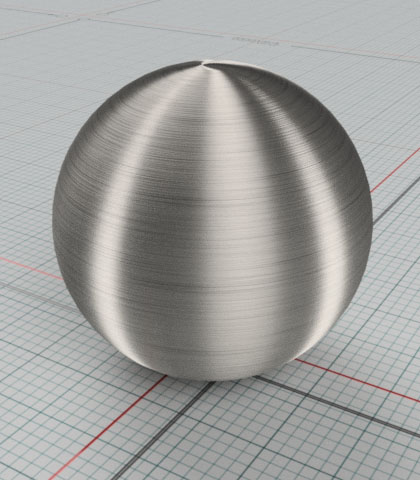
The Highlights Control parameters let you tweak those physically correct settings and also add anisotropy to the reflection shape to simulate brushed surfaces.
- Anisotropy
- This value (or texture) sets the amount of anisotropic effect, with 0 being no anisotropy, and 1 being extremely anisotropic.
- Keep in mind that the material need to have a certain amount of roughness for the effect to become visible. Anisotropy is not possible on a mirror surface.
- This value only narrows the highlight shape. The size is determined by the surface roughness. So, to obtain a strong anisotropic effect, start with a high surface roughness and then a high anisotropy value. As the highlight is narrowed in one direction, you get back sharp reflection edges on one directions.
- Examples of different Roughness amount with same Anisotropy.
Roughness = 0.25, Anisotropy = 0.95
Roughness = 0.5, Anisotropy = 0.95
Roughness = 0.85, Anisotropy = 0.95
- Examples of same Roughness with different Anisotropy amount.
Roughness = 0.5, Anisotropy = 0.0 (reference)
Roughness = 0.5, Anisotropy = 0.35

Roughness = 0.5, Anisotropy = 0.75
- Orientation
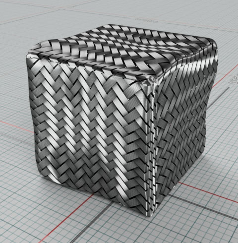
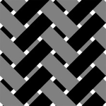
- Turns the direction of the anisotropic effect. It can also be a texture if the effect varies, like in a circular brushed metal or a woven carbon fiber.
-
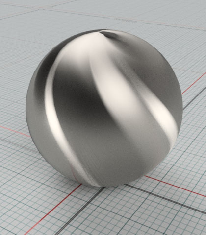
Orientation = 30 degrees
Orientation = 90 degrees
Orientation = 135 degrees
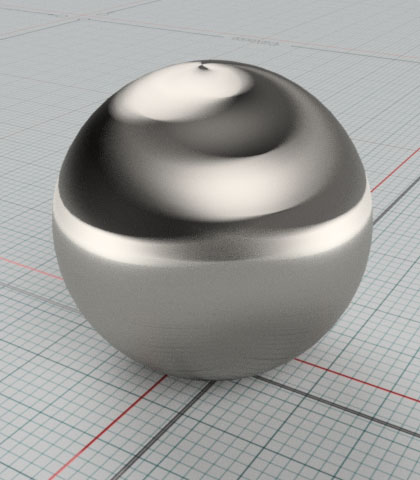
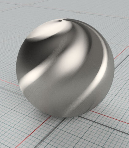
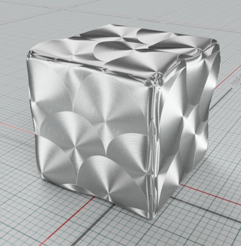
- Examples of materials using an Orientation texture.
-
- Color
- The highlight (or Reflection) color is usually white for physically accurate results. It is possible to use gray values to fade distracting reflections when accuracy is not the goal.
- A black color would eliminate any reflection even at grazing angles.
- Color can also be used to eliminate reflections on surfaces where a bump texture is used for grooves or pits. As those grooves and pits would not fully reflect the environment because of ambient occlusion, a texture fading or eliminating reflections where they occur would make the result much more realistic.
-
Dimmed reflection (grey Color) to recreate a black chrome material
No reflection (black Color). Note darkening of edges since this is a physically impossible material.
Texture used to eliminate reflections on surface pits and deep scratches
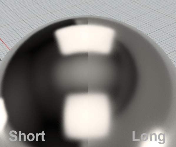
- Shape
- The microfacet surface model has two options for the size of a reflection falloff, Short (Beckmann) and Long (GGX).
-
- Using a combination of Anisotropy, Orientation, and a Color texture you can get a brushed metal effect
-