Set Up Layout Instruments
This topic presents some good principles for setting up and configuring your layout instruments or total station when working with the Layout app.
These instructions are intended as a guide only. Refer to the manufacturer's recommendations to fully calibrate your total station.
Coordinate Systems
There are several coordinate systems used by surveyors. The State Plane Coordinate System is typically used in the United States. Others include UTM, Northing (Y) and Easting (X), and True North. Coordinates may be communicated in:
- Latitude, longitude, and elevation.
- Y, X, Z: Northing (Y), Easting (X), and elevation (Z).
- X, Y, Z: Easting (X), Northing (Y), and elevation (Z). CAD software communicates using this system.
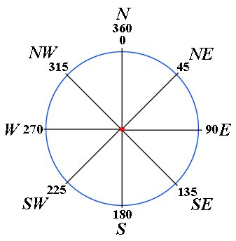
Azimuth entry is from 0 to 360 as on a compass. Azimuth or other offsets are not saved as attributes on a point; they are used to compute a new location for the point. The point is moved after the offset entry is finished.

Control Points
By setting control points, you can help ensure that specific points in your model match their corresponding points in the field. When establishing control points, take account of the following:
Always physically check control points on the ground with points in the model to help ensure optimum accuracy.
Set three or more control points to allow you to check angles and distances. Angles are more critical to accurate layout than distance measurement alone.
Check for deviations. A deviation of zero is optimal, but normal real‑world conditions leave about a 0.1875-inch deviation. Deviations of 0.25 inches or more should be verified and noted.
To export a deviation report:
- Open a model.
- Tap

 Layout Points.
 - Tap

 Report.
Note: You can specify the Deviation Report Tolerance and other options in the app Settings menu.
Control points may be provided through a list of coordinates in a PDF, CAD, CSV, or TXT file.
Points are often provided in an offset from the structure or survey monument locations for the site.
If the site has no control, create your own by laying out offset points from the real-world structure using string and tape, and then matching them to the same offsets in the model.
Setup Routines
A setup routine completes the orientation of the total station or GPS equipment with the BIM information and the job site. Without a completed setup routine, the total station has no idea where it is in the world. A standard setup routine includes:
Known point
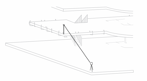
Known points are used to check control points and set up your total station. Place the total station on a known control point and backsight to another known control point.

Control distances
Do not lay out positions beyond the control distance. If two points are 100 feet apart, do not stake out points beyond a 100 foot radius from the total station. Also remember that a greater control distance gives you a more accurate layout.
Resection
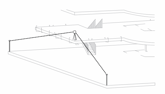
A resection allows you to set the total station in a random location and compute its position by measuring shots to two or more known control points. More angles and greater distances make for a more accurate resection. Try to reference at least three points with an angle between 60 and 90 degrees.

Real-time kinematic GPS settings
To get GPS positions within a centimeter, contact your instrument dealer to configure your Real-Time Kinematic (RTK) GPS with a correction service, and to output NMEA data GGA and GST at a rate of 2 positions per second. Example correction services include a VRS or NTRIP server.
GPS setup
GPS setup allows you to set up and use a GPS on a project that is not in grid coordinates. Some apps call this localization: to translate, rotate, and scale from GPS latitude and longitude to your own coordinate system. To use a model that is already in grid coordinates in the millions (state plane or UTM) from an authoring app like Civil 3D, you should not use Setup since it lowers your accuracy. Instead, simply choose your grid zone in settings.
- Select a point to translate your coordinates to, ideally near the centroid of your project. Tap the Next button once the coordinates are updating and the coordinate quality is good.
- To rotate points into your own system, move to a second point with known coordinates at the far side of your project. Select the point from the model, press Measure, and then the Next button once the coordinate quality is good.
- The app computes the rotation to adjust the GPS data to fit the 2 points. This adjustment is saved for any future use of this model. You should normally not change the setup after collecting some points as you may create a slightly different coordinate system that doesn't match your previous coordinate system.
GPS options saved in Settings
- Select the 'GPS Convert grid to ground' checkbox to turn on or off the application of the grid factor. This scales your coordinates to better match ground distances. Deselect to use grid distances which are shorter.
- Enter a GPS HQ Tolerance distance to have the app warn you if you try to Collect a point with an HQ quality below that number. Enter 0 (the default) to avoid those warning alerts.