An Energy Analysis Model (EAM) is essentially an abstraction of a building’s overall form and layout into a ‘computational network’ that can capture all of the key paths and processes of heat transfer throughout the building effectively. (See How Whole Building Energy Simulation Works)
At its most fundamental level, an EAM is geometry. In this section we’ll focus the fundamental building blocks that make up an EAM, and how to control your architectural BIM model to produce a valid EAM.
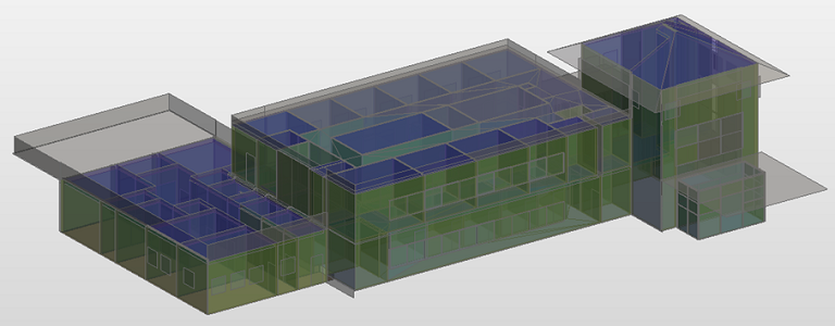
An Energy Analytical Model (from Revit)
There are many tools and methods for creating energy analysis models (even within the suite of Autodesk tools). Therefore, there are two challenges inherent to describing Energy analysis models: 1) Using consistent and precise terminology; and 2) differentiating between the component parts of an EAM which are essentially constant, versus the tools and practices for authoring them which vary widely.
To ensure consistent terminology, this documentation will reference the elements from the gbXML schema, which will be highlighted in italics throughout.
To best address different tools and practices, this documentation starts with explanations of EAMs at the highest level before getting into the details of how EAMs can vary due to different tools and methods.
Basic terminology: Spaces, Surfaces and Zones
The key parts of an EAM are Spaces, Surfaces and Zones. The image below shows the relationship between these elements.
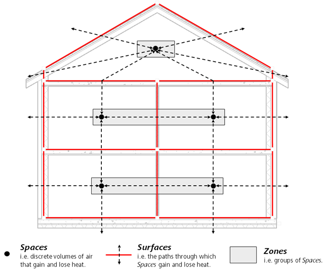
An EAM seen as a ‘computational network’ comprising of Spaces, Surfaces and Zones
Put as simply but completely as possible:
- S paces are discrete volumes (masses really) of air that experience heat loss or gain due to internal processes like occupancy, lighting, equipment and HVAC as well as exchange heat with other Spaces and the exterior environment.
- Surfaces are the paths of heat transfer to or from each Space, including between interior spaces and the exterior environment.
- Zones are groups of Spaces used to establish some commonality between those spaces - such as having the same orientation, the same function, or being served by the same HVAC system.