Surfaces are the paths of heat transfer to or from each Space.
So while Spaces represent discrete masses of air that experience heat loss and gain, Surfaces or more precisely Space Boundary Surfaces, represent the different paths of heat transfer to or from that Space (to other Spaces or the outside environment). The heat transfer happens evenly over the entire area of the Surface.
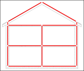
This illustration shows the nature of Space Boundary Surfaces, where it’s been assumed there are five Spaces (Not shown).
Surface Adjacency and Type
The nature of heat transfer through the Boundary Surfaces
Surface Adjacency and Type are two key attributes that dictate some fundamental differences in the way in which each Surface is processed in the energy simulation.
For Adjacency there are only two possibilities: 1) Space which means the Surface is connected to another Space, or 2) ‘None’ meaning the Surface is connected to the outside environment.
It might seem trivial to assign the right type of Adjacency, but some authoring tools can misidentify Adjacency due to certain geometric tolerances like gaps, slivers, or leaks between Surfaces. The result of this misinterpretation is that interior walls can be assumed to have heat loss or gain to the outside, which is clearly very wrong.
In relation to Surface Type considering some of the nuances of the gbXML schema Surface Type could warrant its own post so all I will say about this aspect is that
Surface Type allows the energy simulation to make some basic differentiations of Surfaces based what it represents in the model. For example, roofs and walls, interior and exterior each have different convection coefficients.
Some Surfaces are in contact with the ground, some Surfaces are transparent and transmit light and solar gain while others are Shades (no heat transfer is simulated for Shades, and they simply act to obstruct direct solar radiation to other Surfaces).
It’s also possible to elect a Surface Type as Air. This is common for when large rooms are discretized into more than one Space and the Air represents the fictitious face that subdivides the room.
Again, many EAM authoring tools can struggle to get Surface Type right due to the same issues of geometric precision that affect Adjacency.
Surface Geometry
Heat transfer area and orientation to the elements
A building’s form and layout is represented using Surface Geometry in an Energy Analysis Model. gbXML has two ways to represent Surface Geometry: 1) Planar, and 2) Rectangular.
In both cases, it is most important is to capture each Surface’s overall area and position relative to the sun and wind (when exterior facing) so that the amount of heat transfer across that Surface to or from the Space can be determined by the energy simulation.
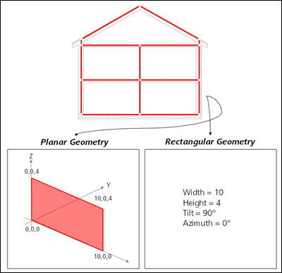
Planar vs. Rectangular Surface Geometry
Surface Planar Geometry is defined using Cartesian Point Coordinates: a series of X, Y and Z coordinates that capture the position, shape and size of each (Planar) Surface.
Surface Rectangular Geometry captures the same key information (area and position of the Surface relative to the sun and wind). However, it simply uses numerical values for height, width, tilt and orientation.
Planar is more commonly used because it represents the actual form and layout of the building with discrete planar Surfaces. Rectangular is more abstract, which makes it difficult to validate visually, and it also cannot account for things like shading from other Surfaces.
Considering its much wider use we’ll only focus on Surface Planar Geometry.
Space and Surface precision
How exactly do you measure everything?
When moving from an architectural Building Information Model to an Energy Analysis Model, there is more than one way to place and measure Spaces and Surfaces.
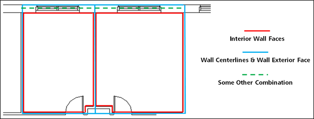
This illustration shows how Space Areas, Volumes and Boundary Surfaces could all be defined in a variety of ways - each yielding a slightly different set of measures and coordinates.
The different options for how these elements helps explain part of the plus or minus 5-10% variation in manually authored EAM measures mentioned earlier. If used only for relative comparisons, then these differences can be negligible. However, these differences present an opportunity for inconsistency and a lack of reliable results between different models.
Another example of varying precision relates to capturing more complex architectural features. Within the context of an Energy Analysis Model, even basic features like curved walls or roofs can create somewhat of challenge because of the limitation of Planar Surfaces. Therefore just as Spaces need discretization, so too do complex building features in order to capture all the heat transfer processes effectively.
The illustration below shows how a simple curved wall could be represented in an EAM with either two or seven faceted Boundary Surfaces. The key question here is what level of discretization is enough; the former may well capture overall area effectively, but will round solar shading effects.
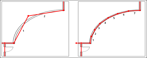
Potential variations in Space Boundary Surface faceting
Surface edge precision
Do they need to form an ‘airtight’ seal? No.
One particular aspect of Space Boundary Surface precision that is important to mention is that Boundary Surfaces do not actually have to be precisely coincident with one another or form an ‘airtight’ seal and relate precisely to the Space Area and Space Volume. This is contrary to what many have come to believe about Energy Analysis Models.
The reality is that Space Area, Space Volume and Boundary Surfaces are all independent items and this means that Boundary Surfaces can have small gaps between them (or even small overlaps). This is important because airtight boundaries can be difficult or very expensive to determine accurately. In reality, a perfectly “airtight” model will have negligible impact on the reliability of the EAM.
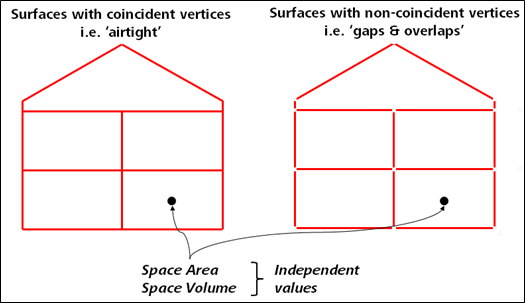
Surfaces with coincident ‘airtight’ vertices (left) vs. non-coincident (right). Both are actually okay.
If this is the opposite of what you have come to believe about Energy Analysis Models from past experience, it’s understandable. Your notions have been shaped by the way many EAM authoring tools work. Most employ some kind of solid or ‘eggshell’ type modeler that combines the definition of Spaces, Surfaces, and their Adjacencies and Type together. When there are gaps in those models, it’s possible that Spaces, Space Types, and Space Adjacencies can be translated wrong to the Energy Analysis Model.
It’s really only ever been the EAM authoring tools that have required airtight boundaries to avoid gaps, slivers or leaks between Surfaces - and not the energy simulation engines or gbXML schema.
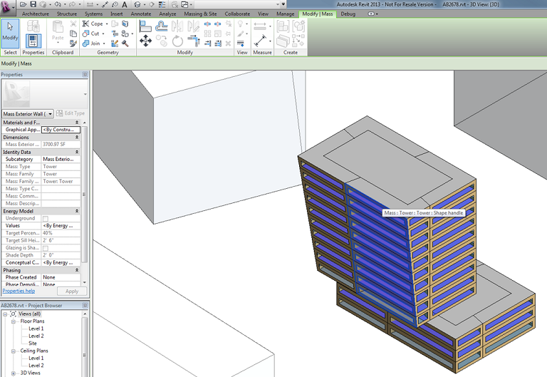
Surfaces selected in a conceptual mass model of Autodesk Revit.
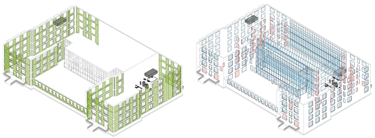
Surfaces shown within an EAM created from a detailed BIM model. Exterior walls are shown on the left. Windows and doors are shown on the right.