Here’s some guidance on how to use and place a 3D camera to approximate a 2D floor plan view for illuminance simulations.
What you need to do to get a good plan view for Revit illuminance simulations is create a non-perspective 3D camera looking straight down, and located between the ceiling and the floor of the level of interest. Typically you should put the camera at the floor plan cut plane about 48” above the floor.
-
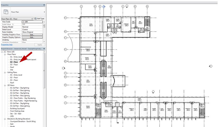
Select a built in Floor Plan view of the floor you want to have your illuminance rendering of.
-
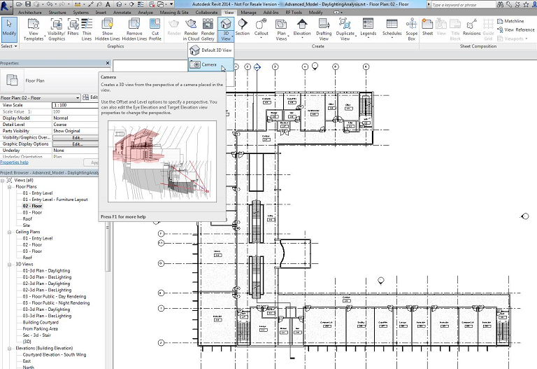
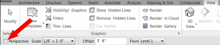
From the View ribbon, select 3D View, then Camera.
-
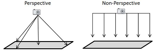
Before placing the camera, it is very important you deselect Perspective to create an orthographic 3D view. This means that the camera is actually a PLANE that measures illuminance values parallel to the direction it’s pointing, NOT a POINT that perceives the scene like the human eye (or camera).
-
Place the camera anywhere in the view. Don’t worry about placement or where you point it. We will change this setting in following steps.
-
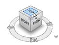
After placing the camera, the camera view will appear. Use the view cube to rotate the camera to the TOP view. This ensures that the camera is looking straight down.
-
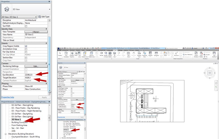
In the camera Properties, change the Eye Elevation so it is below the elevation of the ceiling, but above the elevation of the floor for the level you are interested in.
-
The Eye Elevation is the height of the camera. Best practice is to place the Eye Elevation about 4 feet above the floor plan elevation you are interested in.
-
The Target Elevation is how far the camera will be able to “see” into the model. Change the Target Elevation so it is below the elevation of the floor (any value less than the floor plan elevation you are interested in --typically a value of 0, or the ground plane, will be sufficient).
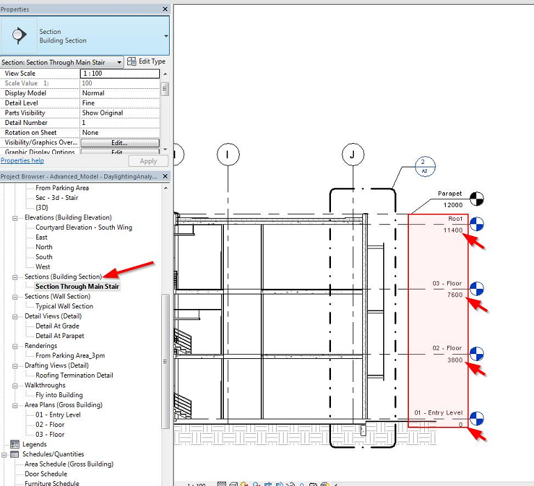
You can use a section elevation to help determine what these values should be. Note the elevations of the floors and ceilings, especially if there are drop ceilings. In the image below, an Eye Elevation of 9000 and Target Elevation of 0 are good settings to view the 3rd floor plan.
-
-
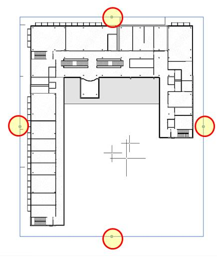
Finally, be sure the Crop Region is visible in the Extents section of the camera Properties window, and adjust the camera crop region extents in the model view so you can see the entire floor plan or whatever portion you want to focus on for your illuminance rendering.