| Quick Start |
- From the View ribbon in Revit
 select Render in Cloud.
 - You will be prompted with render in cloud window. Select a 3D View for the illuminance rendering.
- For Output Type select Illuminance.
- Work through Location/Date, Sky Model, and Legend Settings tabs to set the simulation settings for the rendering:
- Location/Date:
Learn how to set the location for your project on the Specifying the Project Location page.
Define the date and time to be used in the rendering or use date from view option.
- Sky Model:
Use the Sky Model tab to select the sky model that best suits your needs and enter irradiance values appropriate to your location. See Sky Model and Irradiance Value for more information
- Legend:
In the Legend tab set Units (Foot-candles or Lux), Scale Range, and Scale Increment.
- Location/Date:
- Set the image size to set the resolution of the rendering.
- When you have completed your selections, select Start Rendering.
- When your renderings are competed, view the renderings by selecting Render Gallery in the View ribbon from Revit.
- See Rendering and Re-rendering from the Render Gallery if you want to re-render the same scene using different illuminance settings directly from the Render Gallery.
| Detail Workflow |
- 1.From the View ribbon select Render in Cloud.

-
You will be prompted with the following screen. It may take a few seconds for the dialog box to appear. Select a 3D View for the illuminance rendering. You can select one or multiple views to render at the same time. The 3D views in the dialog box correspond to the 3D views you created in your project.Note: It is only possible to do renderings for a 3d model view. However, most lighting and daylighting studies are done for a floor plan view. Please see Setting up Plan View for Illuminance Simulation to properly set-up a camera (a 3D view) to get a clean 2D floor plan.

-
For Output Type
select Illuminance. 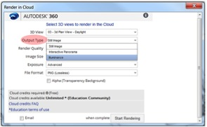
-
After selecting Illuminance, you will be prompted to select the Location/Date, Sky Model, and Legend Settings. Work through these tabs to set the simulation settings for the rendering.

-
Location/Date
The location for the illuminance rendering is always taken from the Revit Model Location. You can learn how to set the location for your project on the Specifying the Project Location page.
The date and time to be used in the rendering can be set in the dialog box. Alternatively, all 3d views contain a setting for the date and time, and this setting can be used automatically. This may be a setting used from a previously conducted Solar Study , or a date and time used simply to visualize shadows in the Revit 3d model view. You can choose to use those settings for the rendering by checking the box below the date field. These settings, along with the location, will be used to dictate the position of the sun in the rendering.
Be sure that your time is set using the 24 hour clock (i.e. 0:00 denotes midnight and 15:00 denotes 3pm).
-
Sky Model
The Sky Model tab features 6 different sky models for the illumination rendering, and also allows you to specify the sun’s intensity (irradiance). Use this tab to select the sky model that best suits your needs and enter irradiance values appropriate to your location.
Good sources for weather data with irradiance values are Green Building Studio, where you can download CSV format weather data for your Revit project location, or the DOE weather data site. See more about how to do this in Sky Models & Irradiance Values.
-
Legend

In the Legend tab you can set:
-
Units (Foot-candles or Lux) – the measure of luminous flux per unit area
-
Scale Range:
-
You can choose to specify the minimum and maximum values
-
Alternatively, you can select “Automatic” to have the scale’s range set based on the minimum value and maximum value (95th percentile) calculated in the simulation with 10 proportional subdivisions.
-
-
Scale Increment:
-
By default, a linear scale is used with 10 proportional subdivisions based on the range chosen.
-
If you choose Logarithmic, the scale will be logarithmic so that you can more easily visually distinguish between values in the lower portion of the range while still capturing very high values.
-
This scale is particularly useful when you select an “Automatic” range because it’s important to be able to distinguish between zero and 2,000 lux for interior lighting design. With a linear scale, the “Automatic” range often renders these critical values within the same color increment.
-
The human eye can function over a huge range of illuminance values – and a logarithmic scale better represents how we perceive levels of brightness.
-
-
-
See the Autodesk Sustainability Workshop for more on measuring and perceiving light
-
Location/Date
-
Set the image size to set the resolution of the rendering. Note that the resolution will influence how many cloud credits the rendering will cost you. You can find more information here .
-
When you have completed your selections, select Start Rendering.
-
When your renderings are competed you will be notified with a pop up window in the lower corner of the Revit screen, and by email if you selected that option. You can view the renderings by selecting Render Gallery in the View ribbon from Revit. You will need to login to Autodesk 360 in order to access the images. Your Autodesk 360 account is the same as the account you use for Revit.