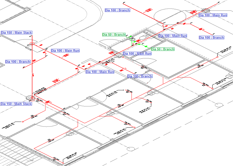
The following procedure summarizes the process of coordinating a public health system.
- In CADmep, open the desired model. This example used a model named "Public Health System".
Public Health System Main Stack at 150.00 Dia
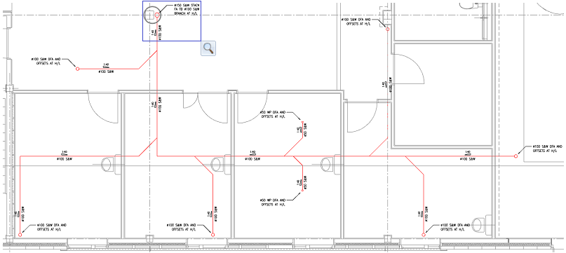
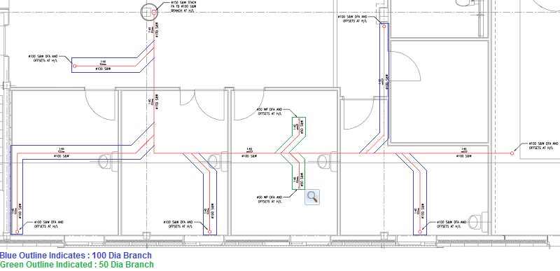
- In the view, zoom into the area of the stack location "Dia 150 S&W Stack FA TB Dia 100 S&W Branch at H/L", as indicated in the upper left area of the building layout.
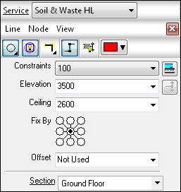
- In the Service drop-down, select Soil & Waste HL.
- Click
 New Design Line.
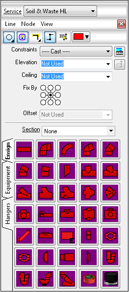
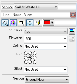
- To create the main stack run of the public health system, in the Service pallet, on the Entry tab, click the Constraints drop-down, and specify 150.
- For Elevation, specify -500. When the Design Line is applied to the building layout, the first start point will be located at -500mm.
- As indicated on the Fix By option, this does not need to be changed. With the point set in the central point indicated the Design Line will be co-ordinated on the central point of the Fittings.
- For Section, specify Ground Floor. Now set, the Design Line will apply the information of the actual section, to the fittings which are going to be located within the building layout.
- At the top of the Service pallet, click Line
 Create. Using snap functionality, select the center point of the circle indicated on the public health system layout. The Design Line will automatically set to the previous elevation of (-500).
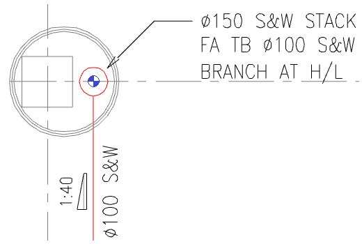
- To set the height of the stack, set the Elevation to 4150. To automatically set the Design Line to the appropriate height, click
 Add Riser, the Design Line will extend to the new elevation at 90 degrees. To finalize the stack, right click or press Enter.
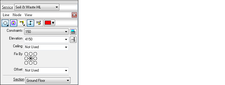
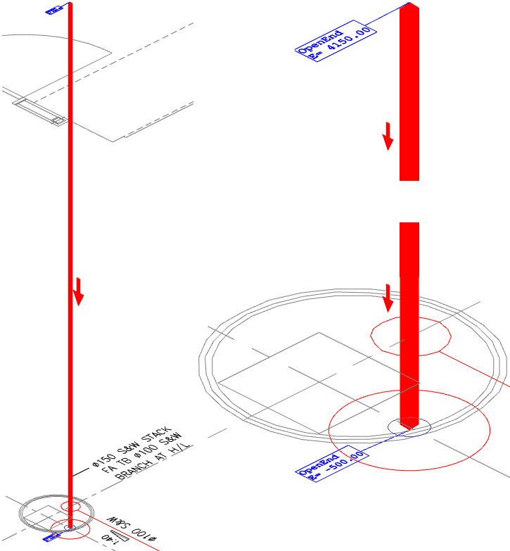
The public health system main stack at 150.0 Dia. is complete.
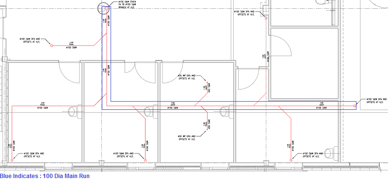
Public Health System Main Run at 100.0 Dia
- In the view, zoom into the area of the stack location "Dia 150 S&W Stack FA TB Dia 100 S&W Branch at H/L", as indicated in the upper left area of the building layout.
- At this stage of the coordination, you do not need to click New Design Line because the command is already active. If this is selected, the active Design Line will change color from the active Constraint color in this example Red, to a Grey shade indicating an in active system. To re-activate the required public health system, double-click on the line to activate.
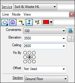
- To create the main run of the public health system, within the Design Line dialog, in the Constraints drop-down, specify 100.
- To set the height of the main run, set the Elevation to 3550.
- As indicated on the Fix By option, this does not need to be changed. With the point set in the central point indicated the Design Line will be co-ordinated on the central point of the Fittings.
- To set the appropriate ceiling height for each room location, the ceiling dialog must be entered. In this example, the ceiling has been made constant from the FFL of (2600.0).
- For Section, specify Ground Floor. Now set, the Design Line will apply the information of the actual section to the fittings which are going to be located within the building layout.
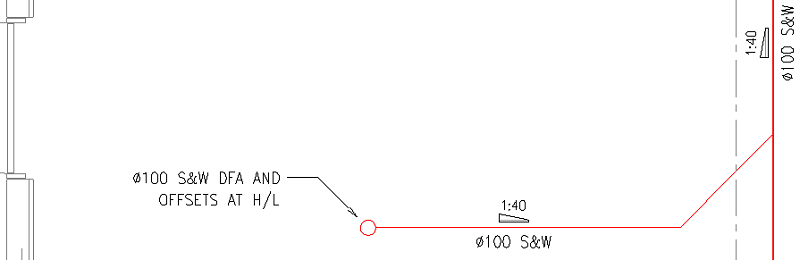
- At the top of the Service pallet, click Line Create, and using Snap functionality, select the center point of the circle indicated on the public health system layout. The Design Line will automatically set to the start point of the Design Line at the elevation of 3550.
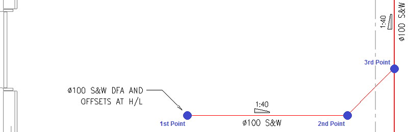
- Co-ordinate the Design Line through the building layout. Using snap settings are essential to enable selecting the appropriate locations on the building layout as indicated below:
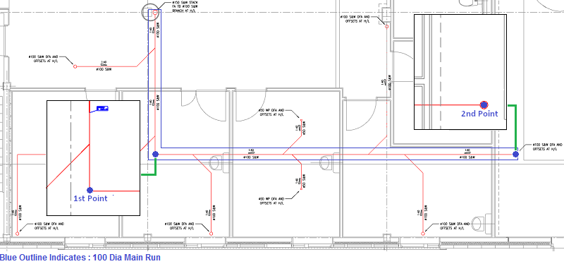
- Select 1st point , with the assistance of snap points.
- Select 2nd point , with the assistance of snap points.
- To finalize the main run, right click or press Enter.
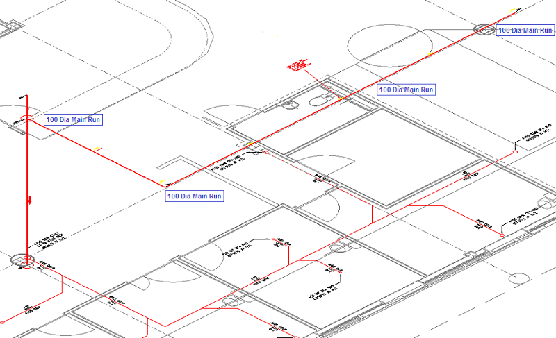
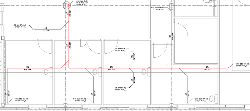
The public health system main run at 100.0 Dia. is complete.
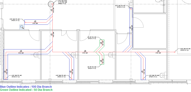
Public Health System Branch Runs at 100.0 Dia
- In the view, zoom into the area of the stack location "Dia 100 S&W DFA AND OFFSETS AT H/L", as indicated in the upper left area of the building layout.
- To create the Dia 100 branch run of the public health system, in the Service pallet, set the Constraints to 100.
- To set the height of the main run, set the Elevation to 3550.
- As indicated on the Fix By option, this does not need to be changed. With the point set in the central point indicated, the Design Line will be co-ordinated on the central point of the Fittings.
- To set the appropriate ceiling height for each room location, the ceiling dialog must be entered. In this example the ceiling has been made constant from the FFL of (2600.0).
- For Section, specify Ground Floor. Now set, the Design Line will apply the information of the actual section to the fittings which are going to be located within the building layout.
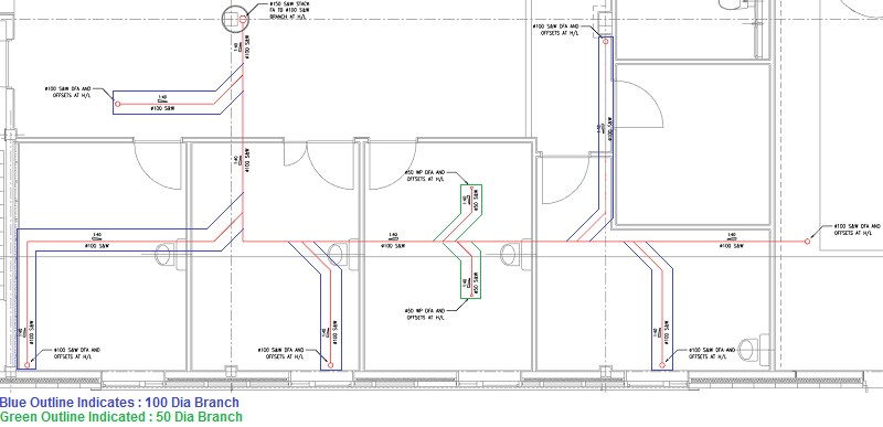
- At the top of the Service pallet, click Line Create, and using Snap functionality, select the center point of the circle indicated on the public health system layout. The Design Line will automatically set to the start point of the Design Line at the elevation set previously (3550).
- Co-ordinate the Design Line through the building layout. Using snap settings are essential to enable the selection of the appropriate locations on the building layout, as indicated below:
- Select 1st point, with the assistance of snap points.
- Select 2nd point, with the assistance of snap points.
- Select 3rd point, with the assistance of snap points.
- To finalize the "Dia 100 Branch", right click or press Enter.
- Repeat the above stages for the outstanding Dia 100 branches within the model.
The pubic health system branch at 100.0 Dia. is complete.
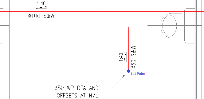
Public Health System Branch Runs at 50.0 Dia
- In the vie, Zoom into the area of the stack location "Dia 50 WP DFA AND OFFSETS AT H/L", as indicated in the lower right area of the building layout.
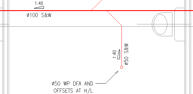
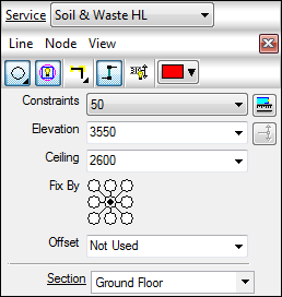
- To create the Dia 50 branch run of the public health system, in the Constraints drop-down, specify 50.
- To set the height of the main run, set the Elevation to 3550.
- As indicated on the Fix By option, this does not need to be changed. With the point set in the central point indicated the Design Line will be co-ordinated on the central point of the Fittings.
- To set the appropriate ceiling height for each room location, the ceiling dialog must be entered. In this example, the ceiling has been made constant from the FFL of (2600).
- For Section, specify Ground Floor. Now set, the Design Line will apply the information of the actual section to the fittings which are going to be located within the building layout.
- Click Line Create, and using Snap functionality, select the Center point of the circle indicated on the public health system layout. The Design Line will automatically set to the start point of the Design Line at the elevation set previously (3550).
- Co-ordinate the Design Line through the building la. Using snap settings are essentia l to enable the selection of the appropriate locations on the building layout, as indicated below:
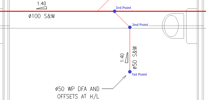
- Select 1st point, with the assistance of snap points.
- Select 2nd point, with the assistance of snap points.
- Select 3rd point, with the assistance of snap points.
- To finalize the Dia 50 Branch, right click or press Enter.
- Repeat the above stages for the outstanding Dia 50 branches within the model.
The pubic health system branch at 50.0 Dia. is complete.
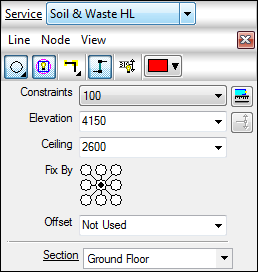
- Public Health System Branch Riser Runs at 100 Dia
- In the view, zoom into the area of the stack location "Dia 100 S&W DFA AND OFFSETS AT H/L", as indicated in the upper left area of the building layout.
- To create the Dia 100 branch run of the public health system, in the Servuce pallett, set the Constraints to 100.
- To set the height of the main run, set the Elevation to 4150.
- As indicated on theFix By" dialog, this does not need to be changed. With the point set in the central point indicated the Design Line will be co-ordinated on the central point of the Fittings.
- To set the appropriate ceiling height for each room location, the ceiling dialog must be entered. In this example, the ceiling has been made constant from the FFL of (2600).
- For Section, specify Ground Floor. Now set, the Design Line will apply the information of the actual section to the fittings which are going to be located within the building layout.
- Click Line Create, and using Snap functionality, select the end point of the line on the public health system layout, as indicated below:
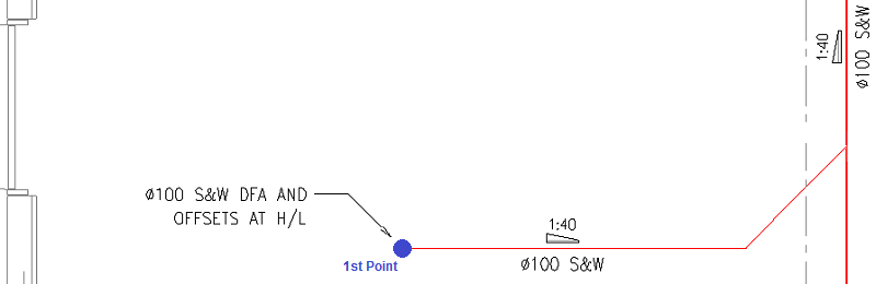
- To automatically set the according height, Select Add Riser, the Design Line will extend to the new elevation at 90 degrees. To finalize the branch, right click or press Enter. Note: A circle is displayed on to the layout, indicating a rise location.
- Repeat the above stages for the outstanding Dia 100 branches within the model.
The pubic health system branch riser runs at 100.0 Dia. is complete.
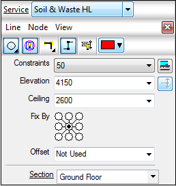
- Public Health System Branch Riser Runs at 50 Dia
- In the view, zoom into the area of the stack location "Dia 50 WP DFA AND OFFSETS AT H/L", as indicated in the upper left area of the building layout.
- To create the Dia 50 branch run of the public helath system, in the Service pallet, set the Constraints to 50.
- To set the height of the main run, set the Elevation to 4150.
- As indicated on the Fix By option, this does not need to be changed. With the point set in the central point indicated the Design Line will be co-ordinated on the central point of the Fittings.
- To set the appropriate ceiling height for each room location, the ceiling dialog must be entered. In this example, the ceiling has been made constant from the FFL of (2600).
- For Section, specify Ground Floor. Now set, the Design Line will apply the information of the actual section to the fittings which are going to be located within the building layout.
- Click Line Create, and using Snap functionality, select the end point of the line on the public health system layout, as indicated below:
- To automatically set the according height, Select Add Riser, the Design Line will extend to the new elevation at 90 degrees. To finalize the branch, right click or press Enter. Note: A circle is displayed on to the layout, indicating a rise location.
- Repeat the above stages for the outstanding Dia 50 branches, within the model.
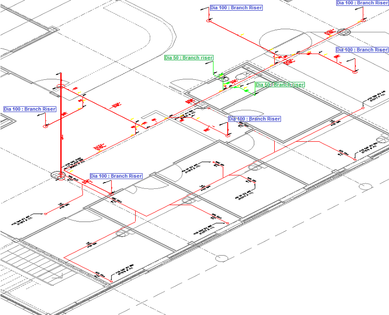
The pubic health system branch riser runs at 50.0 Dia. is complete.
Note: The Design Line coordination of the public health system requires further coordination and modification. See Drainage Tool - Design Line Example for information on how to configure appropriate falls and elevations within the system.