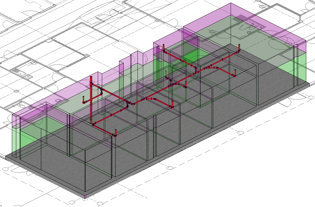
The following procedure describes how to use the drainage tool features with Design Lines.
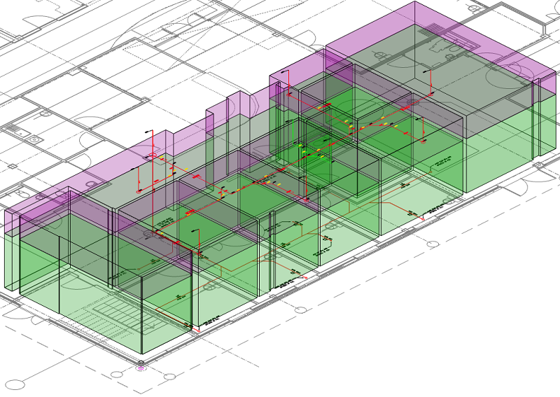
- Review the following public health drainage system models (schematic layout and Design Line Co-ordinated). Note: Falls do not need to be applied when co-ordinating the system throughout the building.
Public Health System - Schematic Layout
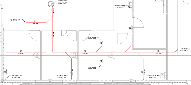
Public Health System - Design Line Co-ordinated
- With the model open in CADmep, click
 Design Line, and then, in the Service Pallet, click Line
  Drainage Tool to access the Drainage dialog.
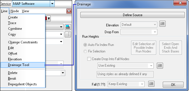
- On the Drainage dialog, click Define Source, and select the Design Line end node at the lowest point of the public health system, as indicated below. The Source Node location has been re-positioned so all the flow arrows within the system will automatically orientate to the correct direction of flow.
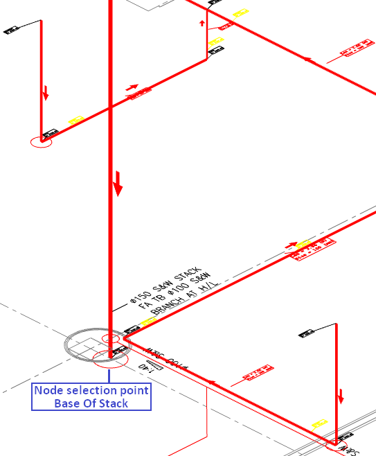
- The public health system has been co-ordinated to flow to the lowest point of the stack. Consideration must be taken in account for the furthest point to fix, for all the corresponding connections to fall correctly as required. To achieve this, use the Run Height tools.
Within the Drainage Tool, click Auto Fix index Run, then Select All Open Ends And Base Stacks. The system will now highlight all Open Ends & Base Stacks. By selecting Enter, the command will calculate the furthest distance from the inserted Source Location once automatically determined this will be set to Fixed to maintain the previous set height of that fitting.

Note a manual selection of fixing Open Ends And Base Stacks can be user applied. See Drainage Tool - Run Heights for various options.
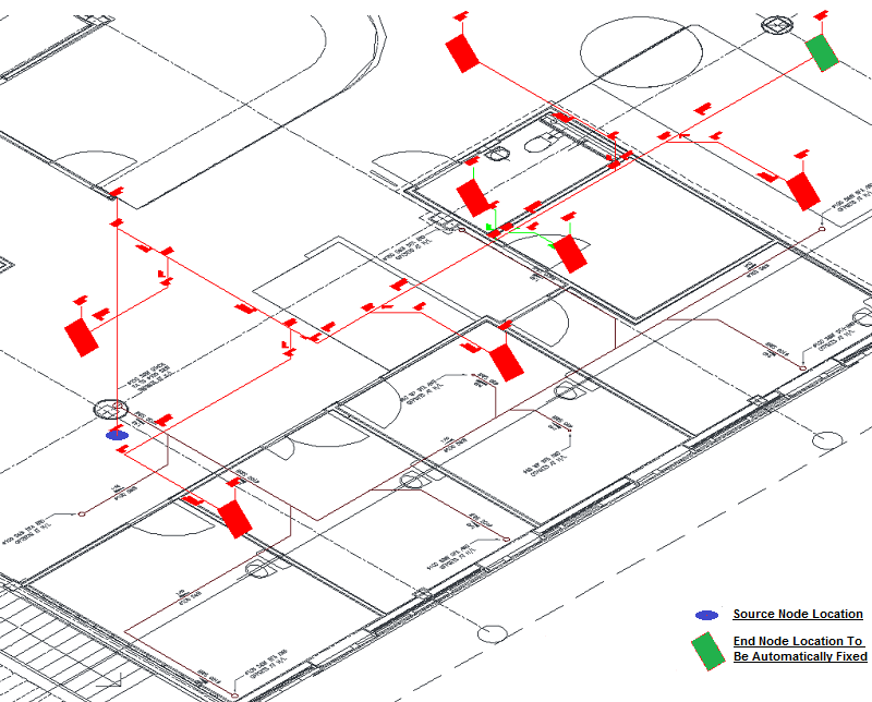
- To apply a fall on the entire drainage system, select from the drop-down menu Fall (1:??) 40.0. This will raise or lower all the Open ends and Stack Bases fittings to the appropriate height required. Any fittings manual selected to be fixed will maintain the height previously configured.

- To finalise and apply the configured drainage system settings, select OK. The system will now be co-ordinated, as illustrated below:
