For oval and round ends of fittings, the length of the extension or collar for can be set automatically by the program, depending on the connector used at that end. This can then be controlled using specifications.
Double-clicking on a connector in the table displays the details dialog for that connector.


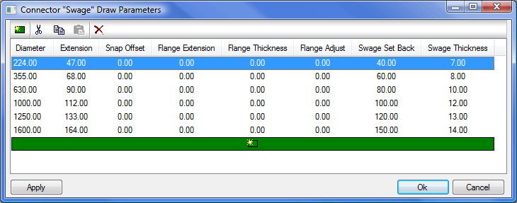
If the library is Round or Oval, then the length of the collar associated with the connector is determined by the Collar Allowance column. The extension is set within Breakpoints, click the Breakpoints button to bring up the following table.

Here it is possible to set up the parameters relating to the connector extension. New parameters are created by clicking New
 and can be deleted by clicking the Delete icon
 . The following fields are displayed:
Diameter: Defines the Diameter Breakpoint in the table.
Extension (A): Defines the overall size of the Auto Extension added to the end of the item to which the connector is attached. This should be at least equal to the Flange Thickness value.
Snap Offset: Defines the distance of the node from the end of the connector to allow for gaskets, sealant, weld prep, etc.
Flange Extension: Defines how far the flange protrudes perpendicular to the body of the item.
Flange Thickness: Defines the thickness of the flange.
Flange Adjust: Allows the user to move the flange along the body of the item.
Swage Set Back (B): Defines the location of the Node Snap point.
Swage Thickness (C) : Defines the thickness of the swage joint.
The image below displays how these parameters define the connector.

When taking off or editing a fitting, set the pattern dimension for the Extension / Collar to Auto, and the software will pick up the sizes specified in the Connector Draw Parameters. If the pattern dimension can not be set to Auto, the fitting does not support this feature.
