The Square to Round pattern is a commonly used fitting with many variable dimensions and options. Similar to the Taper pattern, it often has a double offset, in which case it is essential to understand which offset dimensions are being requested, and how to change them if necessary. The offsets and other features of the Square to Round pattern are detailed below.
Offsets: The amount that a Square to Round offsets is defined by the value entered in the Offset Width (E) and Offset Depth (F) fields on the Dimensions tab during pattern takeoff.
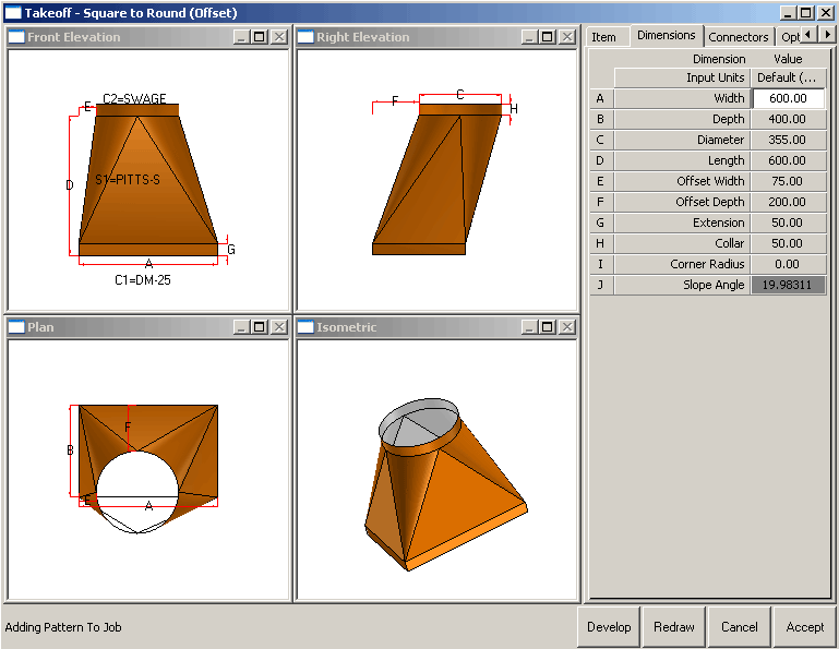
Offset Width (E): This dimension controls the offset left to right, across the width of the duct. This can be seen in the top left view of the image above. This can be an entered value, Flat Left, Flat Right or Central. In this case, entering a zero value gives the same result as choosing Flat Left.
Offset Depth (F): This dimension controls the offset top to bottom, across the depth of the duct. This can be an entered value, Flat Bottom, Flat Top or Central.
The direction in which entered values are measured is controlled by the settings for Offset Width (7) and Offset Depth (8) on the Options tab. By default, on a standard installation, these are set as shown below.
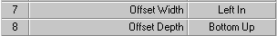
Offset Width: The options available are Left In, Left Out, Right In or Right Out. For details on these options, see Taper Pattern.
Offset Depth: The options available are Bottom Up, Bottom Down, Top Up or Top Down. For details on these options, see Taper Pattern.
Takeoff Dialog Options Tab
The Square to Round pattern also has some pattern options that are exclusive to this pattern. These are explained below.
Cross Break: This option lets you determine how many parts the fitting will be made. The options are 2, 4, 1 or 8. If 1, 2 or 4 is selected, the position of these breaks will depend on the value of the Seam Position described below. When set to 8, 4 flat side parts and 4 round corner parts are always produced, regardless of the Seam Position setting.
Length Break: The user can enter a value here to determine the number of times that the development will be broken across the length of the pattern. The breaks will always be at equal spacing along the centerline of the pattern. The parts are joined to each other using the allowances set up in the seam specified for Length Break S2 on the Connectors tab.
Diameter Type: This lets you specify the diameter type that will be applied. The choices are Nominal, Outside or Inside.
Seam Position: Specifies where the seam will be placed on the part. The options are:
- If Width is selected, the seam will be positioned in the center of the rectangular side that forms the width of the duct.
- If Depth is selected, the seam will be positioned in the center of the rectangular side that forms the depth of the duct.
- The Shortest Side option places the seam on the center of the rectangular side that forms either the width or depth of the duct, depending on which is shorter.
- The Longest Side option places the seam on the center of the rectangular side that forms either the width or depth of the duct, depending on which is longer.
Marker Type: This option determines which type of marker notch will be applied to the fitting. The options are:
- If Notch is selected, a vee type notch is used. The size is determined by the Marker Notch options in the Pattern database.
- The Slit option places a straight up, straight down slit in the pattern. The depth is determined by the Marker Notch options in the Pattern database.
- If no marker notches are required, select None.
Input: This option specifies whether the length of the Square to Round will be determined by entering a length or an angle. Select either Length or Angle. Whichever is selected is active in the Dimensions tab, and the other is displayed visible but 'greyed out' (not selectable), allowing the user to see the setting, but not adjust it.
Offset Width & Depth: These fields are described above.
General Information: This section includes some additional information that is relevant to the Square to Round pattern
Fold Notches: Forming the Square to Round pattern often requires fold breaks along the length of the round corners. Notches can be placed on the round end to indicate the position of these folds. The number of fold notches is set in the pattern database. Click File Setup
Database
Fittings
Pattern Options Notches tab.
Setup
Database
Fittings
Pattern Options Notches tab.
Note: The position where the flat sides meet the round corners is always marked with a Vee Notch as defined in the Pattern database.
Rectangular End Notches: Extensions and connector allowances are applied straight out from the rectangular end. On parts that contain a rectangular corner, this forms a vee shape where the 2 sides meet. This is not a vee-notch. I is the true development. Connector notches will be applied to these sides if possible. In some cases, depending on the entered dimensions, the 2 sides will form an angle greater than 180 degrees. They will be shaped into the part. In this case, metal is actually lost from the connector allowance or extension, and it is not possible to apply the connector notches. When this occurs, either a marker notch or a slit will be applied, depending on the setting in Database
Fittings
Pattern Options Notches tab. If a slit is used, the depth will be equal to the whole of the straight extension. When the seam is positioned through the middle of a rectangular side, the notch associated with the connector is not used. Instead, the notch used is determined by the Notch For Connector Split setting specified in the Database
Fittings
Pattern Options Notches tab
Notch For Connector Split setting.