In CADmep, the Alias command lets you display additional CADmep item information. The information text entered into the Alias field is commonly used to display abbreviations, such as FD and VCD on equipment.
Setting the Alias Text
Before the Alias can be displayed, it must be defined in the item template.
- Right click the item to be modified, and select Properties from the menu. (This can be done in Item Folders or Service Templates.)
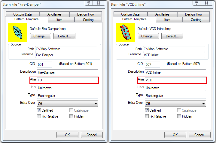
- Click in the Alias field and enter the value to be displayed; for example, FD and VCD as shown in the examples above.
- Click OK.
Defining the Text Style
- Click
 Edit Main Database
  Takeoff tab CAD Settings Annotation tab.
 - Scroll down to Alias Text options.
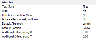
- The Style box is used to specify the AutoCAD Text Style to be used. If the Text Style Sizes is not present, then Standard is used by default.
The following options are available:
- Text Style: Specifies the text style. If the text style does not exist, the "Standard" text style is used. Text height, width, font, and so on, come from the Text Style that is defined here. If you are only displaying in paper space, text height should be the size required for plotting.
- Auto: Checking this option forces CADmep to apply the Alias text as each item is initially drawn. Enabling this option is not recommended, as it may lead to a cluttered drawing. The Alias can be applied when the drawing is finished. This only applies to Bought Out Items when used with the Alias command.
- Hide text in Vertical View: Hides stacked annotation in vertical views; for example, for a riser viewed in Plan, only the base items' annotation is displayed.
- Rotate after manual positioning: An option to rotate the Size label; useful if the Label alignments option does not allow desired alignment because of UCS or item rotation.
- Default Alignment: Sets the annotations' alignment: View, Length or Connector (default = Length).
- Default Position: Sets the annotations' alignment: Below, Middle or Above (default = Below).
- Additional Offset(s) X, Y: Allows additional offsets from the default position.
For more information, see CAD Settings, and scroll down to the Alias Text options.
- Click OK.
Using the Alias command
- Draw the items as normal.
- In the CADmep toolbar, click the Alias icon
 .
. - Select the items on which the Alias is to be displayed. This can be done using any AutoCAD normal selection commands.
- Right click to execute the command.
The Alias text should now be displayed. The Alias text can be moved and rotated using AutoCAD grips or the CADmep  Move Text and
  Rotate Text commands.
Additional Notes:
-
Selecting and reapplying any of the CADmep label commands toggles the label on or off.
-
If the label is toggled off then on again, it will remember its original position and rotation.
-
If no Annotation is displayed, check that the AutoCAD Text Style has been setup correctly.