The CAD Settings section of the Database dialog controls various aspects of both the manufacture parameters and the drawing parameters of CADmep items. These are some of the primary settings used to manage the various aspects of how CADmep controls the drawing of items.
To access the CAD Settings:
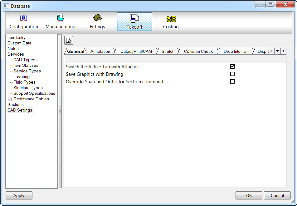
- Click the Database
 Takeoff
CAD Settings.
Takeoff
CAD Settings.
The CAD Settings are organized into the following tabs:
- General
- Annotation
- Output/Print/CAM
- Stretch
- Collision Check
- Drop Into Fall
- Display
General Tab
Switch the Active Tab with Attacher: This option allows users to configure the functionality for the attacher to change between numerous tabs within a service template when various items are selected with the model.
Override Snap and Ortho for Section Command: When this option is enabled, any Snap and Ortho settings are overridden when using the Section command.
Annotation Tab
The following options on the Annotation tab applies to all text objects. They affect the Item Annotation within the drawing.
For more information on using annotation in CADmep, see the Drawing Annotation Fundamental Training video.
General: The following general CAD settings are listed in this section.
Show Text in 3D Mode: This setting allows Annotation to be displayed in isometric views. If this setting is not selected then annotation text will only be displayed in orthographic view. e.g. Plan / Front / Back.
Only Display Text in the PAPER Space Viewports: Specifies the option for Annotation to be displayed in Paper Space only or in Model and Paper Space. Showing text in Paper Space allows for real world text units.
Model Space Text Size: Specifies the text size in model space.
Prompt for Text Positions: Prompts the position when adding: Numbers, Sizes, Levels, Sets, Length & Alias labels.
Value Multiplier: This option can be used to change the Annotation values without objects having to be redrawn. The main use would be to change the annotation values from Imperial to Metric (Scale factor 25) of from Metric to Imperial (Scale factor 0.04) e.g. Scale factor set to 1, Duct size annotation 500x500 (Metric). Set scale factor to 0.04 Duct size annotation changes to 20x20 (Imperial).
Number Text: The settings in this section apply to number text.
Text Style: Specifies the text style for number text.
Auto: Specifies number text to Auto.
Hide text in Vertical View: When selected, text is hidden in vertical views.
Rotate after manual positioning: When selected, text is automatically rotated after manual positioning.
Box for number: Draws a box around a number.
Default Alignment: Specifies the default alignment to be aligned along the view, lengthwise, or aligned with the connector.
Default Position: Specifies the default position to be middle, below or above.
Additional Offset along X\Y: Lets you specify an additional offset for the text along the X and or Y axis.
Lock Leader in Position when Moving: Locks the leader in position when the text is moved.
Discard Leading Zeros when Re-Numbering: Leading zeros are discarded when renumbered.
Size Text: The settings in this section affect size text.
Text Style: Specifies the style for size text.
Auto: Specifies size text to Auto.
Only annotate changes (when Auto): When Auto is enabled, only changes are annotated.
Hide text in Vertical View: When selected, text is hidden in vertical views.
Rotate after manual positioning: When selected, text is automatically rotated after manual positioning.
Default Alignment: Specifies the default alignment of the text to be along the view, lengthwise, or aligned with the connector.
Default Position: Specifies the default position of the text to be above, below, or in the middle of the item it is associated with.
Additional Offset Along X\Y: Lets you set an additional offset for the text along the X and or Y axis.
Format: Specifies the format.
Precision: Specifies precision.
Diameter Symbol: Specifies a location for a diameter symbol, or can be set to none.
Round\Oval Symbol: You can insert symbols to be used for rounds or ovals.
Always report Internal Size: When selected, internal sizes are always reported.
Append Insulation Abbr.: When selected, an abbreviation for the insulation is appended.
Append Service Abbreviation: When selected, an abbreviation for the service is appended.
Level Text : The settings in this section affect the level text.
Text Style: Specifies the style for level text.
Auto: Specifies level text to Auto.
Only annotate changes (when Auto): When Auto is enabled, only changes are annotated.
Hide text in Vertical View: When selected, text is hidden in vertical views.
Rotate after manual positioning: When selected, text is automatically rotated after manual positioning.
Default Alignment: Specifies the default alignment of the text to be aligned along the view, lengthwise, or aligned with the connector.
Default Position: Specifies the default position of the text to be above, below, or in the middle of the item it is associated with.
Additional Offset Along X\Y: Lets you set an additional offset for the text along the X and or Y axis.
Format: Specifies the format.
Zero Suppression: When enabled, zeros are suppressed.
Precision: Specifies the precision for the text.
Round to Nearest: When selected, the text is rounded to the nearest value selected here.
Report Levels from Section Datum: When selected, level values are reported (measured) starting from the section datum.
Report from model Extents: When selected, level values are reported (measured) starting from model extents.
Include Lagging: When selected, lagging is included in level text values.
T.O.D.: The text typed in here is displayed next to level text for T.O.D.s.
B.O.D.: The text typed in here is displayed next to level text for B.O.D.s.
Centerline: The text typed in here is displayed next to center line level text values.
Use same Settings for Round: When selected, the same settings are used for rounds.
Suffix: Specifies a suffix that is displayed at the end of level text values.
Stack Text: When selected, text is stacked.
Ignore Level Block for ToolTip Report: When selected, the level block is ignored on ToolTip reports.
Offset Text: The settings in this section affect offset text.
Text Style: Specifies the style for offset text.
Auto: Specifies offset text to Auto.
Only annotate changes (when Auto): When Auto is enabled, only changes are annotated.
Hide text in Vertical View: When selected, text is hidden in vertical views.
Rotate after manual positioning: When selected, text is automatically rotated after manual positioning.
Default Alignment: Specifies the default alignment of the text to be aligned along the view, lengthwise, or aligned with the connector.
Default Position: Specifies the default position of the text to be above, below, or in the middle of the item it is associated with.
Additional Offset Along X\Y: Lets you set an additional offset for the text along the X and or Y axis.
Format: Specifies the format of the text.
Precision: Specifies the precision for the text.
Tolerance: Specifies the tolerance for the text.
Flat Top\Btm: The text specified here is displayed for Flat Top\Btm.
Set Up\Down: The text specified here is displayed for Up\Down.
Centerline: The text specified here is displayed for center lines.
Offsets Measured from Bottom: When selected, offsets are measured from the bottom.
Display Direction Arrow: When selected, directional arrows are displayed.
Arrow Dimension Style: Specifies the style for dimensional arrows.
Alias Text : The settings in this section affect alias text .
Text Style: Specifies the style for alias text.
Auto: Specifies alias text to Auto.
Only annotate changes (when Auto): When Auto is enabled, only changes are annotated.
Hide text in Vertical View: When selected, text is hidden in vertical views.
Rotate after manual positioning: When selected, text is automatically rotated after manual positioning.
Default Alignment: Specifies the default alignment of the text to be aligned along the view, lengthwise, or aligned with the connector.
Default Position: Specifies the default position of the text to be above, below, or in the middle of the item it is associated with.
Additional Offset Along X\Y: Lets you set an additional offset for the text along the X and or Y axis.
Dimension Text : The settings in this section affect dimension text.
Dimension Style: Specifies the style for dimension text.
Auto: Specifies dimension text to Auto.
Hide text in Vertical View: When selected, text is hidden in vertical views.
Default Alignment: Specifies the default alignment of the text to be aligned along the view, lengthwise, or aligned with the connector.
Default Position: Specifies the default position of the text to be above, below, or in the middle of the item it is associated with.
Additional Offset Along X\Y: Lets you specify an additional offset for the text along the X and or Y axis.
Include Gasket in Dimension: When selected, gaskets are included in the dimension.
Only Dimension Non Standard Strts: When this is selected, only non-standard straights are dimensioned.
Position Relative to Connector End: When selected, dimension text is positioned relative to the connector end.
Use Dimensions text height when in Paper Space: When selected, the dimension text height is displayed in paper space.
Dimension Round straight Node to Node: When selected, round straights are dimensioned node to node.
Output / Print / CAM Tab
This section controls how CADmep handles Xrefs and blocks when printing, and handles objects when exporting to CAMduct, or when exporting using BIM 360 Glue.
Include xrefs: This option controls whether CADmep reports include CADmep items from Xrefed drawings. If this option is off only items from the current drawing will be included.
Include nested blocks: This option controls whether CADmep includes items that have been made into blocks.
Explode Wrapped Objects: This option controls whether CADmep reports Wrapped items, that contain more than one Item, as a single Item or as Individual items. i.e. If a Wrapped Item AHU was made of 3 items, A, B and C, enabling this option would show the items on the report as A, B, C. Disabling the option would report the Item as an AHU.
Change Status: When the Change Status After Export To CAM option is enabled, you can specify the value that the item's status is changed to when output to CAM (.CAJ, .ESJ or .MAJ).
Combine Identical Parts: When selected, identical parts are combined.
Output Developments: When selected developments are output.
BIM 360 Glue Upload Format: Specifies the output format for files uploaded to BIM 360 Glue. For more information, see Autodesk BIM 360 Glue Addin.
BIM 360 Glue X\Y\Z Rotation: Specifies the rotation for models that are uploaded to BIM 360 Glue.
Stretch Tab
This section contains rules for how items behave while stretching or filling.
Min Straight Length: Specifies the value for the shortest length a Straight fitting can be. The Max length of a straight fitting is controlled by the Specification.
Min Bend Ext: Specifies the value for the shortest length a bend extension can be stretched back to.
Max Bend Ext: Specifies the value for the maximum length a bend extension can be stretched to.
Min Trans Len: Specifies the minimum length for Taper / Transition items.
Max Trans Len: Specifies the Maximum length for Taper / Transition items.
Don't allow Template Fittings to be Stretched: If set to "No", Templates can be stretched to the database settings above. If "Yes", they will not stretch, new straights added. You can override "No" by holding TAB when stretching.
Stretch existing Items for Fill Tools: When using Fill2Ends commands, stretch existing items, or add in new. (Stretches 1st item selected).
Restrict to use Items for the same Tab:
Allow Couplers from different Tabs: If above is enabled, allow selecting couplers (joints) from different tabs in the service. These values only control the Item while they are being stretched or used in a fill. Items can be edited after stretching to change any values set by the stretch. However, if the items are stretched again, the rules will be re-applied.
Collision Check Tab
These settings affect the behavior of collision checking features. See Collision Detection.
Enable Run Time Collision Detection: Allows the user to enable or disable CADmep collision detection system. Even if this option is disabled the Check command can be invoked from the Command Line when required.
Show Clash in Viewer: Toggles the Collision detection visual interface to be "On" or "Off". If set to "No" the collision is indicated with the Clash marker functionality on the actual model.
Clash Marker Color:Enables the user to customise the color of the marker by the aid of standard AutoCAD color range pallet.
Marker Screen% Size: Enables the user to customise the actual size of the collision marker when a collision is indicated within the model.
Drop Into Fall Tab
This section contains options that control Drop Into Fall behaviors in models.
Entry Angle: Specifies the entry angle used when using the Drop Into Fall feature.
Entry Angle Tolerance: Specifies the entry angle tolerance used when using the Drop Into Fall feature.
Allow Drop Into Fall Nodes: Specifies whether or not nodes are allowed when using the Drop Into Fall feature.
Flex Tee Angles to Fit: Specifies the flex tee angles to fit when using the Drop Into Fall feature.
Line Fill Error Margin: Specifies the line fill error margin used when using the Drop Into Fall feature.
Display Tab
This section contains a variety of options for setting both drawing and display behaviors in models.
Rise - Fall Symbols : The settings in this section affect rise and fall symbols.
Model Space: Specifies the rise and fall symbols used in model space.
Paper Space: Specifies the rise and fall symbols used in paper space.
Clipped View: Specifies the rise and fall symbols used in clipped views.
Rectangular View: Specifies the rise and fall symbols used in rectangular views.
Round Style: Specifies the rise and fall symbols used for round style.
Presentation : The settings in this section affect behaviors that related to presentation.
Number of Faces: Controls the number of faces used to build items. Increasing this quantity will increase the level of detail in the drawing, useful if rendering. However increasing the quantity will also make the memory usage higher. Items can be drawn with a low setting then changed to a higher setting for rendering purposes. After changing this option the drawing will need to be regenerated for the change to take effect.
Only Show Edges of Round in Wireframe Mode: Controls whether faces are displayed on round items or just the edge lines.
Only Show Edges of Line if Pipe Diameter >: If the Diameter of a Pipe Item falls below this value it will only be drawn as a centerline.
Hidden Detail : The settings in this section affect hidden detail behaviors.
Display Hidden Detail as Dashed Line Type: Allows the items hidden detail to be seen as the Linetype set in the CAD Types. If this option is off, Hidden detail will not be shown as dashed lines.
Use Object Color For Hidden Detail: With this option enabled hidden detail is plotted using the same color or pen weight as the object color.
Process Converted 3D Models: Toggles the "Convert3Dmodel" command to include or exclude the hidden detail lines on the item when converting to CADmep entities.
Centerlines : The settings in this section affect centerlines.
Draw Centerline on Round: Toggles centerlines on and off on round items.
In 3D Views: Toggles centerlines on and off round items in 3D Elevations.
Display on 3D Layer: Toggles the constructed center line to be applied on to the 3D Layer of the item.