Some patterns have the Hole option which lets you add items, such as an access panel, for example. Each time the Hole option is selected, a new set of pattern options are added to the pattern to allow the hole configuration. Other patterns, such as structural items, have a rigid set of Hole options. All options are described in the following examples:
- Rectangular Holes
- Round Holes
- Oval Holes
- Holes and Structural Items
Adding Holes to Patterns
Some patterns also allow the option of adding dynamic branch holes. See Creating Dynamic Branch Holes for more information.Rectangular Holes
- Add a Square Bend to the drawing, using the following values:
A Top Width 500 B Depth 500 C Btm Width Equal D Angle 90 E Top Extension 100 F Bottom Extension 100 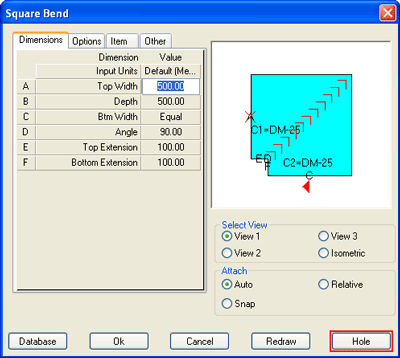
- Click the Hole button.
- Select Back wrapper from the Hole - Select Side drop-down menu.
- Click OK.

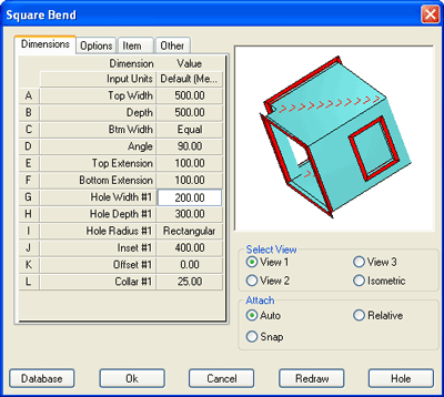
- An extended set of pattern dimensions is displayed. Enter the following values: Note: Each time the Hole option is selected, a new set of hole configuration options are added to the pattern.
G Hole Width #1 200 H Hole Depth #1 300 I Hole Radius #1 Rectangular J Inset #1 400 K Offset #1 0 L Collar #1 25 - Click OK.
Round Holes
To configure oval holes, set Dimension H - Hole Depth #1 - Round , Use Dimension G - Hole Width #1 - to set the Hole Diameter.

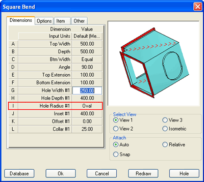
Oval Holes
To configure oval holes, set Dimension I - Hole Radius #1 - Oval.
Holes and Structural Items
Example - Universal Column
- From the Service Selector drop-down menu, select Steelwork Structural from the Structural Group.

- Click the Universal Column icon to display the Add Items dialog.

- Select 203x203x60 from the Description drop-down list.
- Click OK.
- The command line displays the following prompt:

- At the command line, type Y followed by Return to rotate the item before insertion.
- Add the item to the drawing.
- Click OK if prompted by the Fix Relative dialog.
The Universal Column should insert as follows:

- Double left click the item to display the Item Edit dialog.
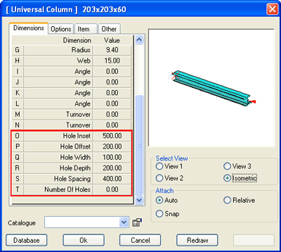
- Fields O - T sets the hole configuration. Enter the following values:
O Hole Inset 500 P Hole Offset 102.50 Q Hole width 100 R Hole Depth 200 S Hole Spacing 400 T Number of Holes 6 
- Adjust the Hole options as necessary. Note: Use the Isometric view and Redraw button to help visualize the changes made.