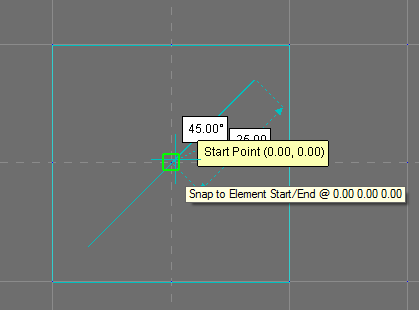
Symbols are used to show placement of objects on to Design Lines. Symbols can be plan view ITM files or 2D DXF drawings that have the 0,0 point through the center of the object.
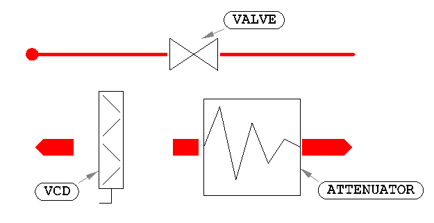
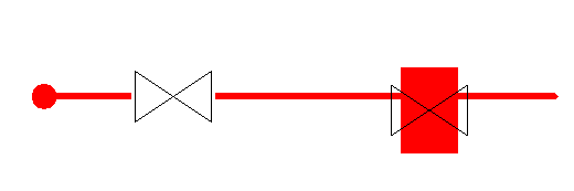
Note: Symbols that are unconnected to Design Lines will not be able to fill in 3D with connectivity rules; they could be missing flange connections. These are highlighted with a red background.
Creating your own Symbols
- Using an external 2D drawing package, or Opus, located from enabling Item Folders
 View Toolbars Item Folders Toolbar, and then selecting the button, as shown below, create the 2D symbol, ensuring the 0,0 coordination is positioned to the center of the part.
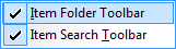

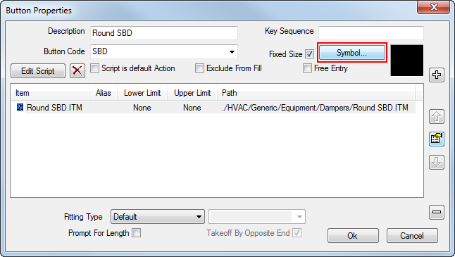
- From your Services view, right-click the button requiring assignment of the symbol, and click Button Properties.
- Select the Symbol button, and browse to the location of the saved DXF, ITM file.
- Ensure the correct format is specified in the "of Type" drop-down.
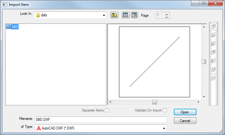
- Click Open, and confirm the Select Layers of the DXF by clicking OK.
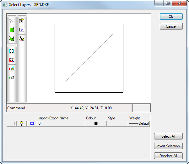
The symbol is assigned to the button and is available for placement onto a Design Line.