The Insert menu contains 2 ways to import parts into a drawing: Import Item and Vectorized Image.
Import Items
To use the Import Items option:
- From the menus select Insert
 Import Item.
The Select Import Item dialog displays.
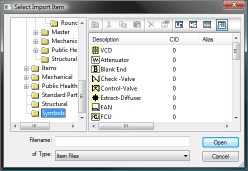
- Browse to and click the desired item, and then click Open.
You are prompted to pick a base point.
- Specify a base point using the mouse or by entering a set of X Y coordinates.
Once the base point has been selected, he following prompt asks if you want to offset the imported item relative to that base point.

The imported item is added to the drawing.
Vectorized Image
It is possible to bring a bitmap (bmp/png) image into the program using the Raster to Vector import function. This option brings in the bitmap image and converts it into a vector graphic that can be edited in Opus.
- From the menu, click Insert
Vectorized Image.
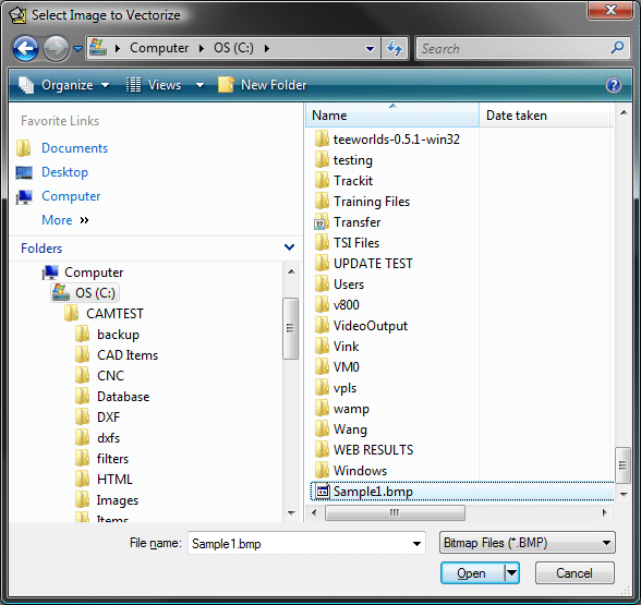
The Select Image to Vectorize dialog displays.
- Specify a name and location of the image file to be imported.
There are 2 types of image file formats that can be imported: Bitmap (*.bmp) and *.png.
- Select the file to import and the Raster to Vector Options dialog displays.

There are a number of presets included with the program, but it is also possible to create your own and save them as presets. To change parameters of a preset, make the changes needed, and when the dialog closes, you are prompted to save the changes or create a new preset file.
The following options are available:
Angle sensitivity: This setting does not depend on the type of element. More sensitivity means that more angles are detected.
Trace Mode: The Raster to Vector uses 2 different Trace Mode parameters for the imported image, you can select whether to use Centerline or Outline.
- Centerline: For Centerlines, the Minimum Pixel Length parameter serves to eliminate artifacts. It is used to remove centerlines which connect to another centerline only at one end and have a pixel length less than the selected value. the side effect of a large value in this parameter may be in a loss of detail.
- Intersect Along Tangents: This option controls X-type intersections. When this option is not selected, a different simplified mechanism is used for lines to cross intersections. Leaving this option unchecked may be useful in situations when poorly defined intersections are present, for example, on a map with several families of intersecting lines.
- Outline: For the Outlines, the Minimum Pixel Length parameter enables you to eliminate outlines which length in pixels is less than the selected value.
There are three elements that can be chosen for recognition: Lines, Arcs, and Curves.
Lines: Detect Orthogonal (Horizontal and Vertical), and Detect 45 Degrees. If, for instance, the 45 Degrees option is selected, then the special check will be done for lines if they can be identified as having 45 degrees inclination.
Arcs: Circles are included as arcs with equal ends. No additional options available.
Curves: There are several additional options to choose from when Curves are selected.
Curve Options: The following Curve options are available:
- Iteration Factor Smoothing is an important part in the curve enhancement mechanism. At each iteration it re-shapes the curve to make it smoother. The number of Iterations defines the depth of the re-shaping. Each iteration can slightly shift the curve, so one may trade accuracy against smoothness. When a high accuracy is required a few (1 to 2) iterations may be preferred. To create fine curves 10 to 20 iterations may be an appropriate choice.
- Constrain Shift by Tolerance This will keep the curve on the black area for shift tolerance 0 or permit is 1 pixel close to black area for tolerance 1. The side effect of Constrain Shift by Tolerance is that it may affect smoothness so it is better not to use it when trying to obtain fine curves.
-
Curve Representation: There are 3 options for representing curves, set using the drop-down menu.
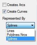
- Splines
- Lines
- Polylines/Arcs: When using this beziers are approximated by arcs and lines. This transformation of beziers into arcs and lines is controlled by the parameter Poly Arc. Larger tolerance gives less arcs.
- Tolerance (Pixels): This option defines the precision with which bezier polynomials represent curves. More tolerance produces less bezier points.
- Conjunction Tolerance: This is applied when one curve at it's end point is tangential to another curve at its inner point. Less tolerance gives smoother conjugation but it can also shift the intersection.
- Preview: Click this button to display a representation of what will be imported.
- Click OK to import the image.
You are prompted to select a base point. This can be selected using the mouse or entered as a set of X Y coordinates.

Next you are prompted to offset the imported item, relative to the allocated base point.