When a Design Line is drawn, node keywords on the Design Line indicate the button code mapping that is associated with the Design Line in order to Fill in 3D. See the node definitions listed in the table below. The node keywords can be displayed on the Design Line by clicking View
 Annotate on the Design Line Takeoff dialog. When this option is enabled, on the node keywords are displayed on the Design Line layer, similar to what is shown in the table below.
If the service includes a fitting that accommodates the node keywords, this will be used when attempting to Fill in 3D. The service buttons can be arranged to ensure that the first button in the service is used before attempting to move to the next available button (using top to bottom ordering). If the service button does not accommodate for the node keyword, button mappings can be used from each service to allow for a combination of fittings.
For example, a Red4Way node keyword could result in a mapping to a Straight and 2 Shoes, or just use a Cross pattern that accommodates the node keyword using its button code. The Cross would be used if the branches are equal. If the branches were reducing, that could mean the Cross pattern is unable to reduce and therefore move to the next available scenario being the two Shoes from the Service Button Mapping tab. With this logic we can determine scenarios and exclude buttons for it to force alternative fills.
The following table lists the default node keywords, and illustrates how they are formed when using Design Line.
| Node Keyword | Example | Description |
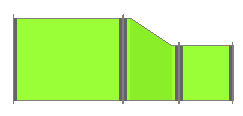
| RedInline |
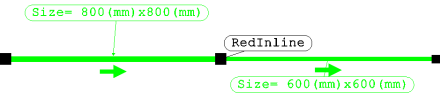
|
2 Lines meet and continue in the same direction with different sizes |
| Bend |
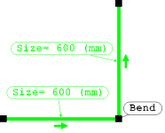
|
2 Lines meet at an angle |
| Offset |
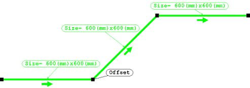
|
2 Lines meet an angle then continue in the same direction as the first line |
| RedILTee |
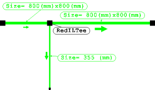
|
3 Lines intercept at an angle in the form of a Tee |
| RedEOLTee |
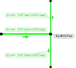
|
The End of 1 line in the flow direction forms a Tee with 2 other lines |
| OpenEnd |
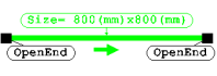
|
Open Ends are positioned if there is no terminal or Source attached to the end of the run. |
| Red4Way |
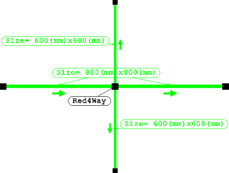
|
4 Lines meet at the same geometric point |
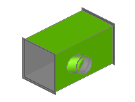
| ShapeChange |
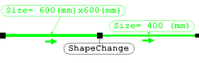
|
Section change from Rect to Round, Rect to Oval |
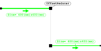
| OffsetReducer |
|
Line is set from the Fix By setting at takeoff leading to an Offset Reducer button code. This particular example shows a Flat left set duct transferring the full width to then become a flat right reducer. Value of movement must be entered prior to selecting new Fix By position.
|
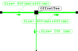
| OffsetTee |
|
Line Fix By position is changed at the point of branch selection. This example shows a flat bottom main run with a central Fix By position for the circular branch. Elevation change of half the depth was required in order to position branch centrally.
|