A variety of methods can be used to set the scale of a PDF underlay. You can set the scale during the Import Underlay process, as described below in Set a Custom Scale Using the Linear Dimension Tool, or after the underlay has been imported, as described in using the USS or AS commands. Note that some file types, such as DXF and DWG files, are already to scale when they are imported as underlays.
Set a Custom Scale Using the Linear Dimension Tool
You can use the Linear Dimension tool to measure and display the number of units for a linear dimension of a selected part in the Select Layers dialog before the PDF underlay is actually imported. Once you know how many units a part dimension is displaying at, you can then set a custom scale using t his information. This can be done on the Select Layers dialog that displays during the Import PDF Underlay process. The steps below describe how to do this.
- Begin importing the desired PDF underlay by right-clicking in the 3D Viewer, and selecting Import Underlay.
- Select the desired PDF, and specify which pages to import if there are multiple pages in the PDF, and click Open.
- On the Select Layers dialog, click the Linear Dimension tool button
 , located on the Dimensions toolbar in the 3D Viewer. For more information, see
3D Viewer Toolbars.
- Next click the Snap to Element Start\End button
 , located on the Snap Mode toolbar, and then click the start and end point of the desired part linear dimension to measure it and add a dimension.
This displays the size of the selected linear dimension in the current drawing units. Once you have this information, you can set a custom scale. For example, if in the model 16 inches is represented by 7.920 units, you would set the custom scale as described below. Use the dimension appropriate for your model and desired result.
- Set a custom scale using this measurement by clicking the Scale drop-down menu and selecting Custom.
- For example, type 16 into the Inch field, and 7.92 8 in the Units field, and click OK.
This would set the scale to have 16 inches represented by 7.920 units for the underlay.
- Use the Linear Dimension tool on the imported underlay to confirm the dimension and scale.
Use the UseSetScale (USS) Command
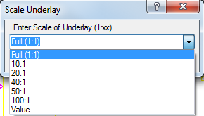
If the scale is known on an underlay that has already been imported, type the UseSetScale (USS) command into the 3D Viewer region, and then press Enter to display the Scale Underlay dialog shown below. Select the desired scale and click OK.

Use the AlignScale (AS) Command
Another method for scaling an imported underlay is to use the AS (AlignScale) command from within the 3D Viewer window, and select two points.
To set the scale of an imported underlay using the AlignScale (AS) command:
- In the 3D Viewer window, type AS.
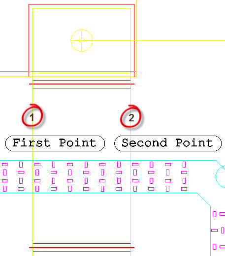
You are prompted to select a First Point, as shown below.


-
In the 3D Viewer window, click in the model to select the first point.
On selection of the first point, for a complete length, it is recommend to use the
 snap option to result in a 90-degree motion. This allows a complete straight line to be drawn when selecting the second point.
Tip: If no annotation is listed in the model, try using a door width for the selection points.
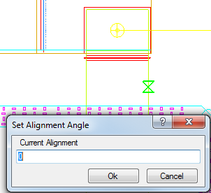
The Set Alignment Angle dialog displays. This displays the current alignment rotation, and lets you rotate the underlay, if required.
-
If no rotation is required, click OK at this dialog.

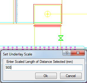
Next the Set Underlay Scale dialog displays, prompting you to Enter Scaled Length of Distance Selected, as shown below.

- In this dialog, enter the known distance in mm or inches, depending on whether you are using a metric or imperial configuration, between the two points selected.
- Click OK and the selected underlay is scaled based on the distance entered.
It is possible to import multiple underlays, all with various scales. Each underlay can be scaled using the above technique and placed into individual layout tabs.