The 3D Viewer includes the following toolbars:
- View Toolbar
- Draw Style Toolbar
- Dimensions Toolbar
- Item Commands Toolbar
- Tools Toolbar
- Snap Mode Toolbar
- Camera Toolbar
These toolbars are also available in the Fab Viewer in CADmep.
Move a toolbar by using the left mouse button to select a grip point on the toolbar, and dragging it to a new position.
View Toolbar

The View toolbar, shown above, includes the following elevation view options:
Plan, Bottom, Front, Back, Left, Right Elevation, as well as the following Isometric Elevations available from a fly-out, or drop-down menu: SW, SE, NE, NW.
Fly Mode, Glide Mode, Walk Mode, Navigate Mode: Fly / Glide Mode presents a moving display of the model similar to a flight simulator experience. Using the mouse and keyboard, Walk Mode lets you navigate through a model presenting the view as if you were walking through it. In Navigate Mode you use the mouse to present a moving view of model as if you were walking through it.
Show UCS Axis, Show Design Line, Show Items, Show Underlays, Show Proxy Graphics, Show Dimensions, Show Zones. (Pull-down Menu)
Viewer Settings: Displays the Viewer Settings dialog. For more information, see 3D Viewer Settings.
List All Commands: Displays a list of all commands that are available in the 3D Viewer. For more information, see 3D Viewer Command List.
Styles: Displays the Styles dialog for setting a variety of style options for the 3D Viewer.
Layer Tool Bar (Drop-down Menu)
Draw Style Toolbar

The Draw Style toolbar, shown above, includes the following options: Wire Frame Mode, 2D Wireframe, Wireframe with hidden line removal, Solid, Shaded, Solid & Lines, Shaded & lines, Transparent
Color By: The Color By drop-down provides a variety of options for displaying the model in the 3D Viewer using preset color conditions. For more information, see Color By Options.
Dimensions Toolbar
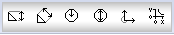
The Dimensions toolbar, shown above, includes the following options:
Linear: A linear dimension only takes either the x- or the y- axis (horizontal or vertical) into consideration. Even if the line is at an angle, only one axis can be measured at a time.
Aligned: The aligned dimension is used to measure the true distance between two points on a drawing.
Radial: The radial dimension measures the radius of any arc selected.
Diameter: This works in exactly the same way as the radius dimension, but reports the arcs diameter rather than the radius. This only works on complete circles.
Angular: The angular dimension will give the angle, in degrees, between the two selected elements, in an counter-clockwise direction.
Ordinate
Item Commands Toolbar

The Item Commands toolbar, shown above, includes the following options:
Set Attacher: Activates the Attacher.
Join: Joins two selected items.
Show Item Numbers, Show Item BOD/TOD, Show Item End Size (Pull-down Menu)
New Design Line, Manage Constraints, Calculate Duct Size, Ductulator, Pick Elevation, Pick Constraint, Erase 3D Items (Pull-down Menu)
End Run
Tools Toolbar

The Tools toolbar includes the following options:
Move Object(s): The Move command lets you select objects and move them to another point on the screen.
Rotate Object(s): The Rotate command lets you rotate the object along the X, Y, or Z axis, dependant on which view you are in.
Edit an Object: The Edit object command lets you open the object in the drawing into the Takeoff dialog again, so new dimensions or parameters can be applied.
Copy Object(s): The Copy command lets you copy the selected objects for pasting into the drawing at a different point. The object that has been copied will be available for pasting into the drawing multiple times until the right mouse button is clicked, or the Escape key is pressed.
Delete Selection: This deletes any selected object from the drawing.
Snap Mode Toolbar

The Snap Mode toolbar includes the following options: Snap Ortho, Snap Polar, Snap to Element Start/End, Snap to Mid-Point/Center, Snap to Nearest, Snap to Node. For more information, see the Object Snap Tracking descriptions in the AutoCAD Help or Opus Snap Modes.
Camera Toolbar

The Camera toolbar includes the following options:
Rotate View: Rotates the model based on a fixed pivot point. As you move the mouse, the model rotates around a pivot point while the view remains fixed.
Zoom To Fit: Zooms in or out to display the extents of the drawing. This results in the largest possible display of all the objects.
Zoom To Selected Region: Zooms to a visual display area specified by two opposite corners of a rectangular window selection.
Store Camera: Store an existing camera within a model.
Retrieve Camera: Retrieve an existing camera within a model.
Add Camera: Add a camera with a user-defined view, (Top, Bottom, Front, Back, Left, Right, Isometric Views.)
Delete Camera: Delete an existing camera within a model.
Rename Camera: Rename an existing camera within a model.
Workspace Features

The Workspace features shown above are available in ESTmep and CADmep for validation, and are not available in CAMduct. For more information, see Workspace.