The following procedure below describes how to set up the Autofold decoiler machine and generate the .DEC file that the Autofold controller can read.
-
Click File
 Setup
Setup Installed Decoiler.
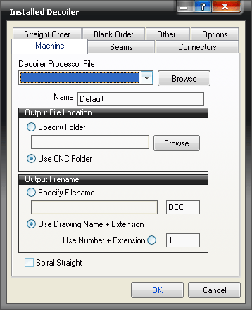
A blank Installed Decoiler dialog displays, unless a previous decoiler has been installed.
- Give the Decoiler a name, such as AUTOFOLD, then click the Browse button.
- Select the autofold.dpl file, which is typically located in the C:\Program Files\Autodesk\Fabrication <version>\CAMduct\DPLs folder, and click Open.
The following dialog displays:

- On the Machine tab, specify the following options:
Output File Location: You can specify here whether the generated DEC file is saved in a specified folder, or if it will use the same folder as NC for a Cutting table will use. This is normally C:\CAM\CNC.
Output Filename: Here you can specify a file name. Use the Job name (Drawing Name) with the specified file extension (in this case DEC) or use a number plus the specified file extension.
NB: File extensions should only be changed if your supplier has setup the Decoiler to accept a specific file extension.
- Click the Seams tab, and specify the following options:
This tab lets you specify which of the seams set up in the pattern database correspond to the seams that can be created in the Autofold decoiler.
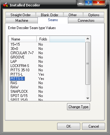
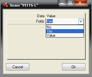
Double clicking on a seam in the list will allow you to change the folds to the seams supported by the decoiler.
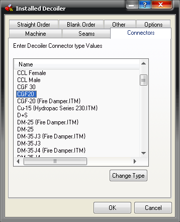
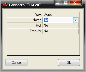
- Click the Connectors tab, and specify the following options:
The Connectors tab lets you link the connectors in the Pattern Database to the connector types supported by the decoiler. The options available determine whether a notch will be applied, whether the connector end will berRolled in the Autofold machine, and, if fitted, whether the duct will be placed in the transfer line on the decoiler.
-
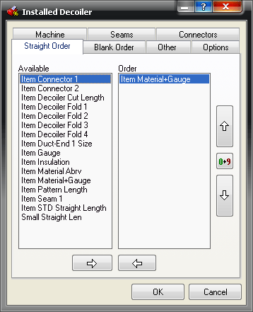
Click the Straight Order tab, and configure it as follows
This tabe lets you specify the order that the Decoiled Straights are put through on the DEC file. By default, this is set to sort the straights by material and gauge.
-
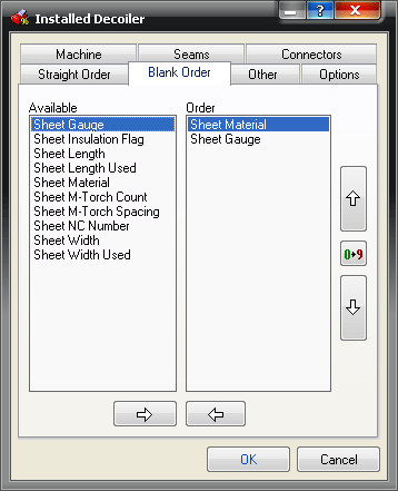
Click the Blank Order tab, and configure it as follows:
If the option to Output Nested Sheet Blanks is set in a Process, then the Blank Order can be set similarly to the order in the Straight Order.
-
Click the Other tab, and specify the following options:
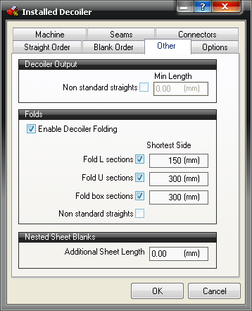
The Other tab specifies whether to Decoil Non standard straights, and determine the minimum length permissible.
The Folds section covers whether the Decoiler is set to do Decoiler Folding, and if so, what the minimum permissible shortest side length is for L sections, U sections, and box sections. Again non-standard straights can be included in this list.
If required, an additional sheet length allowance can be applied to any Sheet Blanks cut on the Decoiler.
-
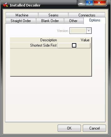
Click the Options tab, and specify the following options:
This tab allows you to force the short end of the duct to go through the folder first.
-
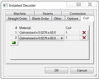
The Coil tab does not need to be configured for this decoiler.
Creating the DEC Output File
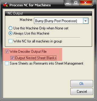
The decoiler output file can be created manually by clicking Utilities  Decoiler Output, or by setting up a process to include "Write Decoiler Output File" as shown below in the Write NC dialog.
