A simple part is defined as having a single outer island within which there could be multiple inner and center cut islands. The outer-most continuous island will be assigned as an "outer". All continuous islands contained within the outer will be assigned as "Inner" islands. Islands that are not detected as being continuous (intentional or not) are assigned as "Center Cut" islands.
- If any continuous islands completely contain further levels of islands, these will be alternatively assigned Outer, Inner.
- If any island is not contained within another island, it will be assigned as an Outer island.
- If a Center Cut island protrudes beyond the boundaries of the Outer island, the part will be contained in an artificial box for nesting purposes. A red box will be drawn around the part icon and the Status "O" for Outer Missing assigned.
- You can change the cut side on any island.
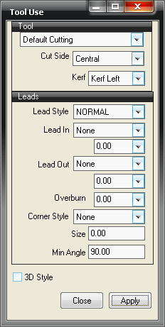
- Left-clicking on the outer island displays the Tool Use dialog.
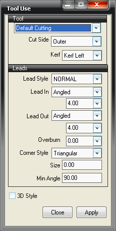
By clicking on the down-arrow next to the Cut Side field, you can choose to make an island Outer, Inner or Central, as needed. As you make a change, note that the leads may also change, as shown below.
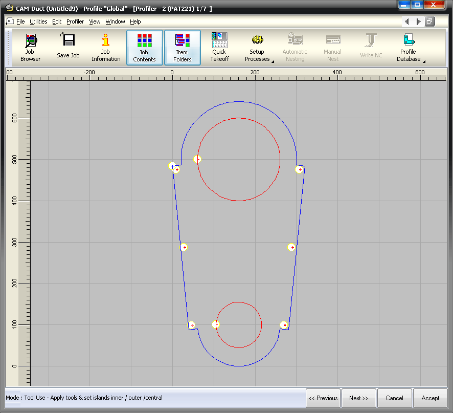
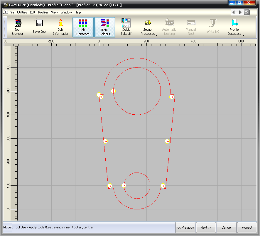
The color of the island will change as the cut side changes. Outer cuts display by default as blue, inner are red, and central are purple, as shown below.

After importing a part, this mode is entered, provided the part does not require repair.
All of the islands should have been defined and the colors should confirm all of the Inner, Outer or Center Cut islands. Small yellow circles indicate where the default Lead Ins and Lead Outs have been placed. To confirm the Tool, Cut Type and Lead In details for any island, click with the left mouse button on any element included in the island. The island will be drawn in the selected color. The default color is yellow.
The Tool Use dialog displays.
Tool: Displays the default tool as assigned by the setting in the database( File
 Setup
Profile Database
Tool Defaults). If other tools are available, they can be assigned here on an island basis.
Setup
Profile Database
Tool Defaults). If other tools are available, they can be assigned here on an island basis.
Cut Side: The Cut Side is important because it determines which side of the cut the tool thickness (kerf) will be applied to.
Kerf: Relates to the thickness of the torch and can be set to Kerf Left, Kerf Right or Kerf Off.
Leads: Displays the default Lead values.
Lead Style: Click here to change the Lead Style. Lead Style Names and values are User defined in File
Setup
Profile Database
Leads. Each Lead Style defines:
- Lead In Type: None, Perpendicular, Straight, Angled, Semi Circle
- Lead In Size: length required
- Lead Out Type: None, Perpendicular, Straight, Angled, Semi Circle
- Lead Out Size: length required
- Over burn: length required.
Corner Styles: Stop start, Clover Leaf and Triangular corner styles can be set up if required. If Profiler detects geometry restrictions, semi-circle leads may be replaced by angled leads. Profiler tries to detect any leads that have been applied in the CAD program. The values detected will be assigned to the Lead Sizes.
Using the Tool Use and Lead In Menu
- The cursor is displayed as a pointer when moving over the part.
- Click on the required island to confirm or change the tool applied, the Cut Side or Lead In/Out values.
- You must press Apply to activate the changes.
- To hide the Tool Use dialog, right click outside it or choose another menu option.
Multiple Island selection
- Hold the left mouse button down and drag a selection window around the required islands. Alternatively, hold the Shift Key down and click the required islands to select.
- Make changes in the displayed Tool Use dialog.
- Click Apply to activate.
Changing the Lead values and Moving the Leads
- As you move over a Lead In position, as identified with a small red circle, the cursor changes to four arrows.
- Right-click to verify or change values.
- A graphic display helps you to see the leads and any over burn.
- Click the left mouse button to drag the Lead In to a new position on the island.
- Center Cut islands will only allow the leads to be applied to the ends of the island.
See also Adding leads to .