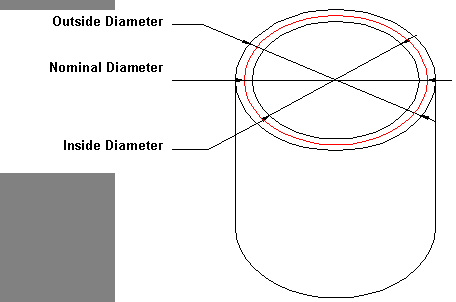
The three diameter types of a circular pipe or fitting are Nominal, Inside and Outside. The terms generally apply to the position that the diameter is measured from. The diagram below shows all three of these measurements dimensioned on a straight pipe.
When working with round fittings and pipe, it is important to establish what diameter type is being used for the development. Within the pattern database, it is possible to set the program to produce developments using one of these types. Some examples of the differences that are encountered with developments when using the various diameter types to measure follow.
- Click File
 Setup
Database
Fittings
Pattern Options
General tab, and locate the Circ\Oval Dev option.
Setup
Database
Fittings
Pattern Options
General tab, and locate the Circ\Oval Dev option.
- For this example, set the Circ/Oval Dev option to Nominal.
- It is also necessary to ensure that the
Effective Diameters are not being used. To do this, click File
Setup
Database
Fittings
Effective Diameters.
- Locate the "Use Connector Dependent Effective Diameters" options and make sure they are unchecked.
Defining the Different Options
Nominal
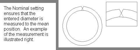
Inside

Outside

The following examples illustrate the implications of these settings, combined with the choices made on the Pattern Options in Takeoff.
Example One
First, with the Circ/Oval Dev setting of Nominal:
- Click Utilities
Item Folders Round folder.
- Select Pattern CID 41, Round Pipe.
Enter the Dimension values as shown below:

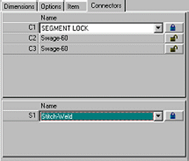
- Click the Connectors tab and ensure the settings are specified as shown below:

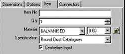
- Click on the Item tab and set the Material Gauge to 0.8, as shown below:
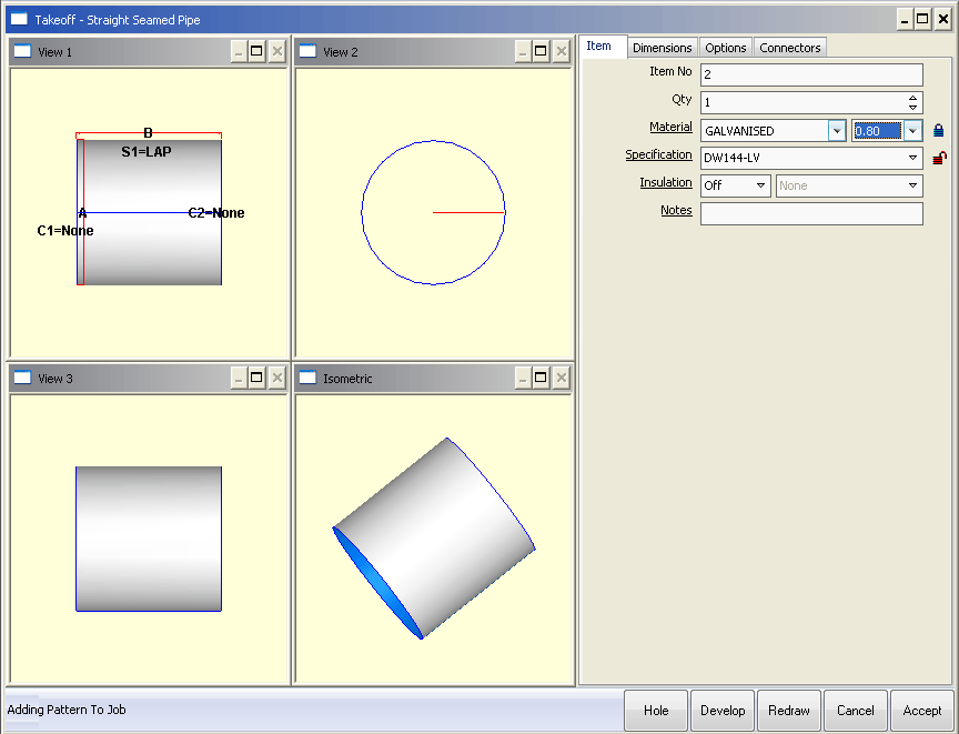
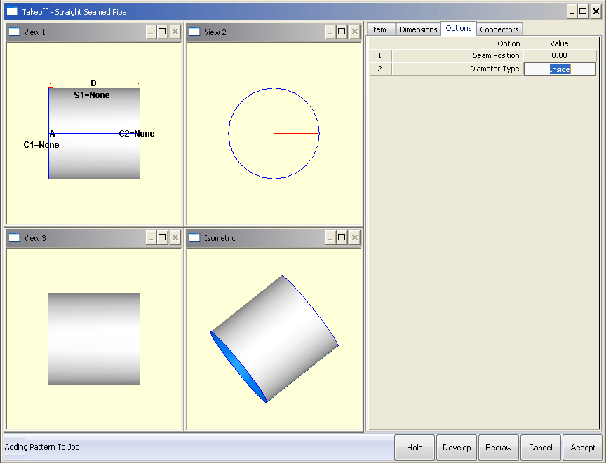
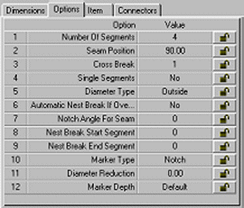
- Click on the Options tab and click in the Diameter Type Value field until it displays Nominal, as shown below:
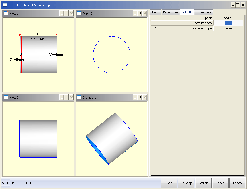
- Click Redraw followed by Develop. The developments should display as shown below. Note the Y Size of 314.159:
- Click End, then click again in the Diameter Type field until it displays Inside.
- Click Develop again. The developments should display as shown below. Note the Y Size of 316.673:

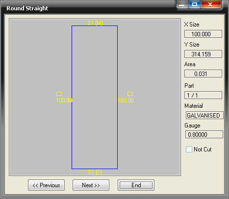
- Click End and click in the Diameter Type field until it displays Outside.

- Click Develop again and note how the developments display as shown below. Note the Y Size of 311.646:

Example Two
- Click File
Setup
Database
Fittings
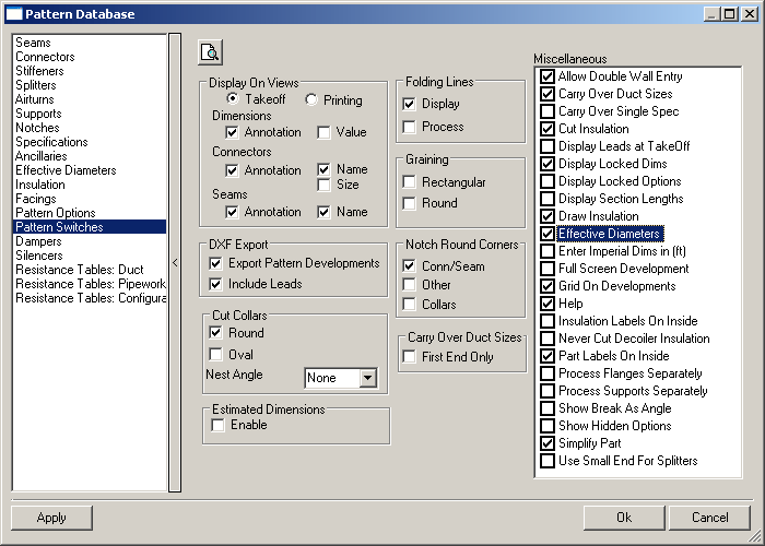
Pattern Switches
General tab.
- Change the Circ/Oval Dev setting to Inside.
- Repeat the previous tests using the round pipe, and note the changes in the Y size in the Developments.
- Set the Diameter Type to Nominal, its value is 311.646.
- Set to Inside and note that it changes to 314.159.

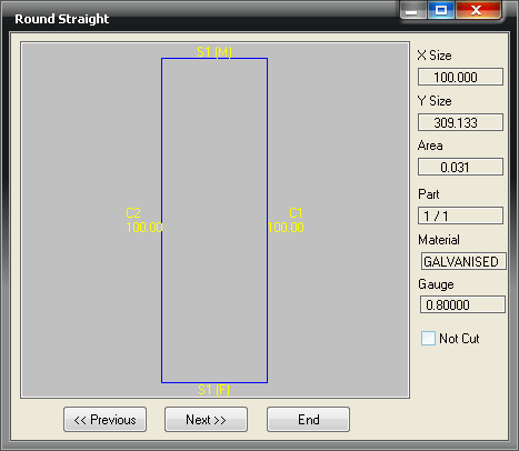
- Finally, set it to Outside and note that it becomes 309.133.
Example Three
- Click File
Setup
Database
Fittings
Pattern Switches
General tab.
- Set the Circ/Oval Dev setting to Outside.
- Repeat the previous tests using the round pipe, and note again the changes in the Y size in the Developments.
- Set the Diameter Type to Nominal, its value is 316.673.

- Change the Diameter Type to Inside, and note that it changes to 319.186.

- Finally, with the Diameter Type set to Outside, note that it becomes 314.159.

Understanding Different Circumferences
The key point to remember is that if the Diameter Development setting is the same as the Diameter Type of a pattern (e.g. both are set to Nominal), then the calculation for the stretch out will be diameter * pi.
The full set of calculations used is as follows:
Nominal Developments
- Nominal diameter type = diameter * pi
- Inside diameter type = (diameter + gauge thickness) * pi
- Outside diameter type = (diameter - gauge thickness) * pi
Inside Developments
- Nominal diameter type = (diameter - gauge thickness) * pi
- Inside diameter type = diameter * pi
- Outside diameter type = (diameter - twice the gauge thickness) * pi
Outside Developments
- Nominal diameter type = (diameter + gauge thickness) * pi
- Inside diameter type = (diameter + twice the gauge thickness) * pi
- Outside diameter type = diameter * pi
Circular Developments
The following example explains all the calculations and variables that effect the developed size of a segmented (or Gored) elbow.
- The image on the left shows a Catalog part or Product List, but the following example is the same for all types of circular developments irrespective of how it was entered.
- Enter the dimensional information as shown in the following image.

- Click on the Develop button, to display the Pattern Development similar to the one below.
Developed X Size:
This reflects the circumference and therefore diameter of the final product. This can be affected by:
- The Diameter entered
- The Diameter Type selected: Outside, Inside or Nominal
- The Gauge
- If the Effective Diameter Table is active
- Seam value
Developed Y Size:
This shows the flat, developed length of the pattern in view. This is affected by:
- Effective Diameter (if applied)
- Throat Radius & Angle
- Dimensions D & E = or if set to Auto, from the active specification
- Connectors selected either manually or automatically from the active specification
- Material & Gauge selected
-
Kerf value
Note: The X & Y value shown may also reflect the Lead-In/Out applied to the part. This can be turned on or off by toggling the Display Leads at Takeoff option in the Pattern Switches section of the Pattern Database.
- Click File Setup
Database Fittings Pattern Switches and locate the Display Leads at Takeoff option.
X Calculations without Effective Diameters Enabled
Listed below are the three different calculations for the circumference of the part depending on the diameter type selected. First, make sure that the Effective Diameters table is not enabled, as previously described.
Diameter type = Nominal:
X = Diam (A) x 3.1416 + S1(M) + S1(F)
Diameter type = OUTSIDE:
X = ( Diam (A) - Gauge ) x 3.1416 + S1(M) + S1(F)
Diameter type = INSIDE:
X = ( Diam (A) + Gauge ) x 3.1416 + S1(M) + S1(F)
X Calculations with Effective Diameters Enabled
Listed below are the two different calculations for the circumference of the part depending on the diameter type selected and with the Effective Diameters table is enabled. First, make sure that the Effective Diameters table is enabled.
- To enable the Effective Diameters table, click File
Setup
Database
Fittings
Pattern Switches
Developments tab, and ensure that Effective Diameters is enabled.
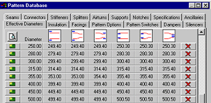
- When using the Effective Diameters table enabled the software will use settings, similar to those in table below right.
The calculations are now as follows.
Diameter Type = OUTSIDE:
X = ( EFF-DIAM - Gauge ) x 3.1416 + S1(M) + S1(F)
Where the EFF-DIAM is the value from Col-2 corresponding with the entered Diameter from Col-1.
Diameter Type = INSIDE :
X = ( EFF-DIAM + Gauge ) x 3.1416 + S1(M) + S1(F)
Where the EFF-DIAM is the value from Col-5 corresponding with the entered Diameter from Col-1.
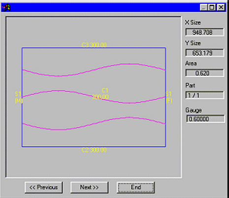
In this example set the bend as in the first image as 300mm Diameter and the following input information as in the images below.
- Note that 0.6mm material, Stitch Weld has been applied (this allows 5mm on both the male and female seam allowance) and that the Diameter Type has been set to Outside.
Therefore the calculation is as follows:
EFF-DIAM = 299.4 therefore X = (299.4-0.6) x 3.1416 + 5 + 5
Therefore X = 948.7
Y Calculations
As mentioned previously, the Throat Radius, Gauge, Kerf and Effective Diameter effect the calculated Y value.
- In this case = (EFF DIAM - Gauge) x Tan 15 x 6 = 480.38
- The C1 field allows the user to apply the relevant connector to the development in the appropriate areas. In this case Segment Lock has been selected which allows 11 + 5 = 16mm. This will be applied 3 times for a 4 Gore Elbow = 48mm.
- If Dims D & E are set to Auto the connectors are allocated from the active specification, Round Duct Catalogs. In this case these are Swage allowances of 2 x 60mm = 120mm.
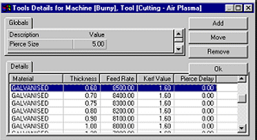
- The Kerf allowance set for the selected material and gauge also effects the Y calculations. To check or set this allowance, click File
Setup Installed Machines. Then select the relevant machine and click on Tools
Air Plasma and Setup.
- In the image below, the Kerf value for Galv. 0.6 = 1.6mm. The calculations need to add this value in 3 times for the common line cut between gores; = 0.48mm.
Therefore, Y = 480.38 + 48 + 120 + 4.8 = 653.18mm
Kerf Compensation
The general Kerf calculations to offset for the Tool Cutting Width can be applied by the Software or applied at the Machine Controller itself. To determine this:
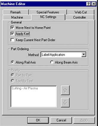
- Click File
Setup Installed Machines and select the relevant machine and click Setup
NC Settings and enable/disable the Apply Kerf option as required.
- If Apply Kerf is not ticked the machine operator is responsible for entering Kerf at the controller. In this case the values entered in the Tool Table should agree with the operators values to ensure the correct common line cut allowance.
Any error in Kerf will affect both X and Y outside dimensions by twice the Kerf error.
To check the software is applying Kerf, input and nest a rectangle + hole and observe the NC Data X and Y Values. They will be offset by the Kerf value. Outside cuts X and Y values will be larger and inside cuts smaller.
Catalog Items
The developments for catalog items are affected by all the variables explained above. Once a catalog item has been established, its developments are stored with it and are not recalculated when the item is selected for manufacturing. The only factor that will affect the development will be the current Kerf value when the part is cut. If the item is edited for any reason, the new development may not be the same if parameters in the database have changed. Care should be taken when editing developments. The user may wish to print out the correct X and Y values for future reference. With multi-user systems, you may wish to restrict some operators editing catalog files. This can be done using the MAPUSER option.
For further information, refer to MAPUSER within this On-line help.
Collar Seam Allowances
The seams applied to collars are slightly different in the fact that they are not applied on a fitting by fitting basis, but are set in the active specification and the allowances of which are included in collar developed lengths.