To assist with calculating stretch-out lengths on circular fittings, the Effective Diameters table can be set up with custom values that can be used for certain diameter types. This table can be customised to reflect the sizes that are most frequently used. The diameter values are then used from the table and substituted into the formulae that are used for calculating the stretch out. See Circular Developments and Diameter Adjusts for more information.
To access the Effective Diameters table:
- Click File
 Setup Database Fittings Effective Diameters.
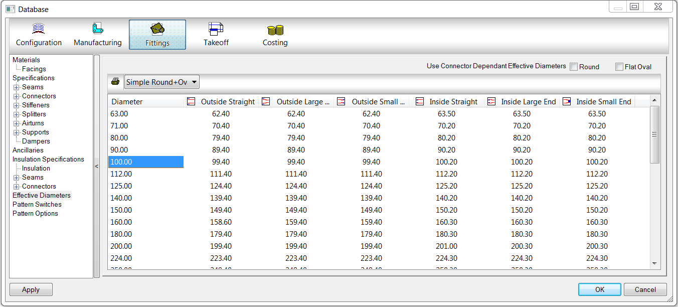
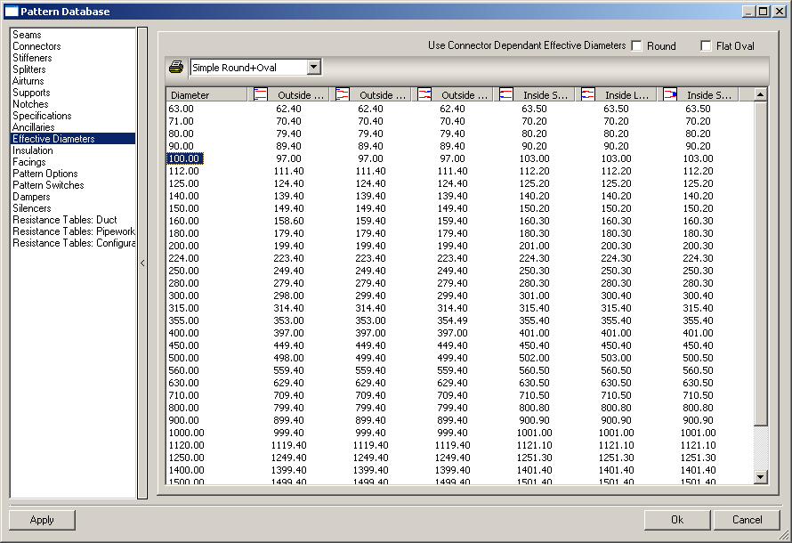
In its default state, the effective diameter table is set up to show commonly entered diameters as used within the metalwork industry. The diameters are used in conjunction with the columns which are described below . Entries can be changed by clicking on the appropriate field and typing in the preferred value. New entries can be added or unused ones deleted by clicking the green 'new' icon or the red cross 'delete' icon as appropriate.
The Effective Diameters table includes the following options available along the top of the table:
Use Connector Dependent Effective Diameters (Round or Flat Oval): When this option is selected for round and or oval fittings, you must also select either Round - Connector Dependent or Oval - Connector Dependent from the drop-down list and then add appropriate diameter vales to build the table for these options. When both the Round and Flat Oval Use Connector Dependent options are enabled, the Simple Round+Oval values are ignored, and the values that are specified for connector dependent round and or oval fittings are used.
Print: Displays a printable report of the currently selected Effective Diameters table values.
Simple Round+Oval: When this option is selected, the simple round+oval effective diameters table that is displayed is used for both round and oval fittings. If you want to only use the simple effective diameters values, for both round and oval fittings, make sure the Use Connector Dependent Effective Diameters options are not enabled. It is possible to enable the Simple Round+Oval values, and also enable just one of the Use Connector Dependent Effective Diameters (either Round or Oval, but not both) to override the Simple Effective Diameters values. (If both the Round and Oval options for Use Connector Dependent Effective Diameters are enabled, then the entire Simple Round + Oval table is ignored.)
Round-Connector Dependent: When this option is selected, the values that are added for to the Round-Connector Dependent table are used to calculate diameters for round fittings.
Oval-Connector Dependent: When this option is selected, the values that are added for to the Oval-Connector Dependent table are used to calculate diameters for oval fittings.
The following columns comprise the Effective Diameters table:
Diameter: The first column lists the diameter that will be entered on the pattern.
The next three columns are used to set the diameters that would actually be used for an internal connection. The last three columns are used to set the diameters that are actually used for an external connection. This provides more control over the use of the values, so that variations for certain connections can be given.
At the top of each of the connection type columns, there is a small conceptual image that graphically represents the type of connection when the value is to be used. The six connections types are described below.
|
|
Outside Straight: This column represents a straight pipe connecting inside to another pipe or fitting. This is conceptually represented in the image by the red lines being positioned inside the blue lines. The value entered into this column is substituted into one of the formulae mentioned earlier when this type of connection is required. This is displayed in the program as Diameter Type field set to Outside. |
|
|
Outside Large End: This column represents a large end reducer connecting inside to another pipe or fitting. This is conceptually represented in the image by the red lines being positioned inside the blue lines. The value entered into this column is substituted into one of the formulae mentioned earlier when this type of connection is required. This is displayed in the program as Diameter Type field set to Outside. |
|
|
Outside Small End: This column represents a small end reducer connecting inside to another pipe or fitting. This is conceptually represented in the image by the red lines being positioned inside the blue lines. The value entered into this column is substituted into one of the formulae mentioned earlier when this type of connection is required. This is displayed in the program as Diameter Type field set to Outside. |
|
|
Inside Straight: This column represents a straight pipe connecting outside to another pipe or fitting. This is conceptually represented in the image by the red lines being positioned outside the blue lines. The value entered into this column is substituted into one of the formulae mentioned earlier when this type of connection is required. This is displayed in the program as Diameter Type field set to Inside. |
|
|
Inside Large End: This column represents a large end reducer connecting outside to another pipe or fitting. This is conceptually represented in the image by the red lines being positioned outside the blue lines. The value entered into this column is substituted into one of the formulae mentioned earlier when this type of connection is required. This is displayed in the program as Diameter Type field set to Inside. |
|
|
Inside Small End: This column represents a small end reducer connecting outside to another pipe or fitting. This is conceptually represented in the image by the red lines being positioned outside the blue lines. The value entered into this column is substituted into one of the formulae mentioned earlier when this type of connection is required. This is displayed in the program as Diameter Type field set to Inside. |


Enabling Effective Diameters in the Pattern Database
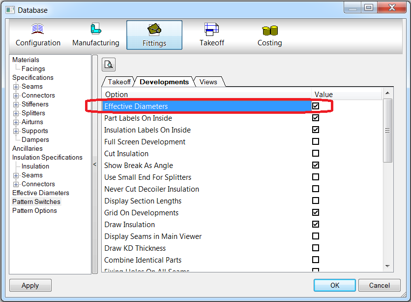
In order for the Effective Diameter values and/or adjustments to be used, the Effective Diameters option needs to be enabled in the Pattern Database.
To enable the Effective Diameters option in the database:
- Click File Setup Database Fittings Pattern Switches.
- Click the Developments tab.
- Ensure that the Effective Diameters option is checked:
Below are two examples of the stretch out being calculated. The first example describes how to calculate the stretch out while not using the Effective Diameter values. The second example describes how to calculate the stretch out using the Effective Diameters values. In both examples, the Pattern Option settings in the Circ/Oval Dev are set at Nominal.
Example One: Not Using the Effective Diameter Table
- Ensure that the Effective Diameter option in the Pattern Switches is not checked (File Setup Database Fittings Pattern Switches Developments tab Effective Diameters).
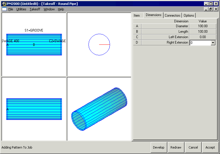
- Go to Utilities Item Folders Round and select Round Pipe (CID 41), and set the Diameter and Length to 100, as shown below.
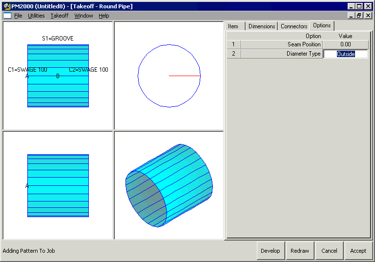
- Click the Options tab and click in the Diameter Type field until it is set to Outside.
- Click on the Item tab, and change the Gauge to 0.8.

- Click on the Connectors tab, ensure that no connectors or seams are used:
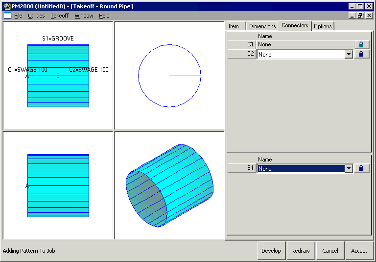
- Click Develop and the Y Size shows as 311.646:

This has been calculated as follows. Using the formula described in the Circular Developments topic, for Nominal Diameter we know that Outside Diameter Type = (diameter - gauge thickness) * pi, which calculates in this example as (100 - 0.8) * pi, or 99.2 * pi, which gives us 311.646.
Example Two: Using the Effective Diameter Table
- Ensure that the Effective Diameter option in the Pattern Switches is enabled (File Setup Database Fittings Pattern Switches Developments tab Effective Diameters).
- Click on Effective Diameters table, again as explained earlier, so that the 100 mm line reads as below:
This will force the program to override its normal calculations by substituting the effective diameter for the actual diameter in the formula, giving the user control over diameter sizes.
- With the same data input as in the previous example, click Develop and the Y Size read as 302.221:

This has been calculated as follows:
Outside Diameter Type = (diameter - gauge thickness) * pi, and as the Effective Diameter of 97 has been used instead of the actual diameter of 100, this calculates in this example as (97 - 0.8) * pi, or 96.2 * pi, which gives us 302.221