The information on print labels can assist the manufacturer in the fabrication of the duct. Labels are customizable and a variety of information that can be included on the label.
The standard part label that comes with a new Autodesk Fabrication product installation looks similar to the illustration below:
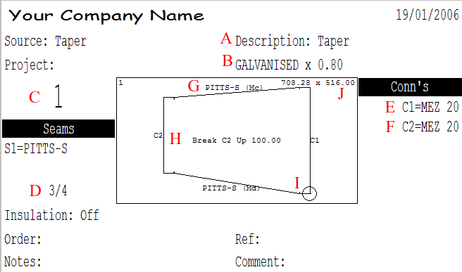
The red letters in the illustration indicate the following areas on the label:
A: This is the Description of the item from the General tab in Item Properties.
B: This is the Material and Gauge that the part is to be cut from.
C: This is the Item Number allocated to the item during Takeoff. It is the same number as displayed in the Job Contents dialog.
D: This is the Part Number and Number of Parts. This example displays Part number 3 out of the 4 Parts that make up the item.
The convention for part numbering will nearly always run in the case of rectangular duct according to the following order:
- Top Panel
- Left Panel
- Bottom Panel
- Right Panel
For bends, the order changes slightly to this:
- Top Cheek
- Bottom Cheek
- Throat Wrapper
- Back Wrapper
Therefore, the part on this label is the Bottom Panel of the Taper.
E: This indicates the Connector to be put on the C1 end.
F: This indicates the Connector to be put on the C2 end.
G: This is the Seam information. After the Seam name, the letters in parentheses can be used to assist in the assembly of the duct. On the example above, the 2 seams are marked (Mc) and (Md). The side marked (Mc) will attach to another part with the label marking the seam (Fc).
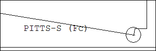
The (Md) will attach to the part that has the seam labeled (Fd).
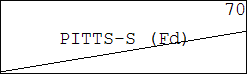
This can be useful to ensure that the proper edges are married together when making tapers with a slight offset, as it can be difficult to differentiate the difference of the slopes visually.
H: This is the bending information. The bending information can be changed to show an angle, as shown below.

To configure the bending information to show as an angle, click File
 Setup
Database
Fittings
Pattern Switches, and then click the Developments tab. Scroll down to the Show Break As Angle option, and enable it.
Setup
Database
Fittings
Pattern Switches, and then click the Developments tab. Scroll down to the Show Break As Angle option, and enable it.
It is important to understand exactly where in a duct system a part resides, and whether the part has been cut with labels on the inside or the outside of the duct.
On the label, it says Break C2 Up 100.00 or Break C2 Up 9<, depending on how you have set up the label. This means that the C2 end of the duct must end up 100mm above C1, or 9 degrees above C1, as shown in the illustration below. This illustration displays the angle as 9.46 which is the true angle size. The information on the label has been rounded.

I: The circle indicates the pierce point on the part. This is also where you should place the label. If you orientate the label and place in this corner then it makes it easier to identify the seams and connector ends. The pierce point is also put at the C1 End unless manually moved in Profiler.
J: This is the blank size of the part.