In CAMduct, the Cut Out commands, located on the Opus drawing toolbar, allow for an island to be drawn inside another island, forming a hole. There are three Cut Out choices:
- Round
- Rectangular
- Slotted Hole
To launch a Cut Out command, do any of the following:
- Click Cut Out and select Round, Rectangular or Slotted Hole.
- Click the Cut Out button
 on the toolbar.
- Type one of the shortcut commands listed below.
Round (Shortcut: CIRCCUT)
Selecting the Round option places a round cut out into the drawing.
- Click Cut Out
 Round, or click the Round button.
The following prompt for radius displays:

- Enter a radius and press Enter.
The Pick Base Point prompt displays.
- Select the base point using the mouse or by typing in the X Y co-ordinates.

Next the Offset prompt displays.
- Enter a set of X Y co-ordinate values, or left-click the mouse to accept the initial base point.

Rectangular (Shortcut: RECTCUT)
Similar to the Round option, this command allows for a rectangle to be drawn, and is created in a similar way to the circular cut out.
- Click Cut Out
 Rectangular, or click the Rectangular button
 , and the following prompt displays:

- In the Width and Height fields, enter the dimensions of the rectangle. Use the Enter key to move through the value fields.
- A corner radius can be applied by entering a Corner Radius value.
- The Rotation field rotates the rectangle on its center axis by the angle entered here.
The Pick Base Point prompt displays.
- Select this using the mouse to pick the base point or by entering the X Y co-ordinates.

The Offset prompt displays.
- Enter a set of X Y co-ordinate values, or left-click the mouse to accept the initial base point.

Slotted Hole (Shortcut: SLOTHOLE)
Similar to the Round and Rectangular options, this command allows for a slotted hole to be drawn, and is created in a similar way to the previous cut outs.
- Click Cut Out
 Slotted Hole or click the Slotted Hole button
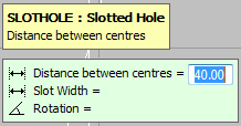
 , and the following prompt displays:.

- In the Distance between centers field, enter the distance between the centers of the 2 circles that make up the ends of the slotted hole. Use the Enter key to move through the value fields.
- The Slot Width is the width of the minimum axis.
- The Rotation field rotates the slotted hole on its center axis by the angle entered here.
The Pick Base Point prompt displays.
- Select this using the mouse to pick the base point, or by entering the X Y co-ordinates.

The Offset prompt displays.
- Enter a set of X Y co-ordinate values, or left-click the mouse to accept the initial base point.
