In CADmep, blocks with attribute definitions can be used to create custom level and size labels. For example, attributes for levels reference the top, center or bottom of objects. Attributes for size reference object width, depth, and diameter.
The following tables list the level and size attributes that CADmep supports.
Level Attributes Definitions
| Attribute Definition | Levels from | Object Reference |
| TOP | Absolute Zero | Top |
| MID | Absolute Zero | Center |
| BTM | Absolute Zero | Bottom |
| STOP | Soffit | Top |
| SMID | Soffit | Center |
| SBTM | Soffit | Bottom |
| FTOP | Elevation Datum (Finished Floor Level) | Top |
| FMID | Elevation Datum (Finished Floor Level) | Center |
| FBTM | Elevation Datum (Finished Floor Level) | Bottom |
Size Attribute Definitions
| Attribute Definition | Size from |
| WIDTH | The Width property on the item definition. |
| DEPTH | The Depth property on the item definition. |
| DIA | The Diameter property on the item definition. |
Create Attribute Definitions
The following ductwork example reports levels from soffit and absolute to bottom of the duct.
- Type ATTDEF at the command line, or click
 in the CADmep toolbar.
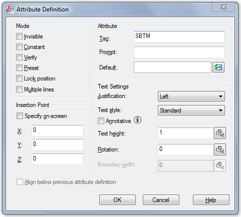
- Type SBTM as the first Attribute Tag.
- The recommendation is to set the Text Style height to a value of 1 as this is eventually scaled by the Level - Text Style height value.
Note: If the Text Style Height field is greyed out, this indicates that the Text Style being used already has a height pre-assigned (Tools
 Format
Text Style).
Format
Text Style).
- Click OK to add the Attribute Definition to the drawing. (If this is not specified, it will be located at 0,0,0).
- Locate the Attribute Definition - Copy the SBTM definition to create the second Attribute Definition below the first.
- Then use the DDEDIT command to rename the Attribute to BTM, as shown below:
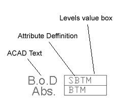
- Use the BLOCK command to create a Block Definition, and select the ACAD Text, Attribute Definitions & Level value box.
Note: Level Blocks should be created on ACAD - Layer 0. By doing this they inherit the currently selected layer properties. This also allows the text layer to be frozen independently from the 3D duct layer. This may require a REGEN.
- Enter a Block Definition Name; for example, Soffit_Absolute.
- Click OK to the Block definition dialog.
Assign the Block Definition to the Service Type
To assign the block definition to the service type:
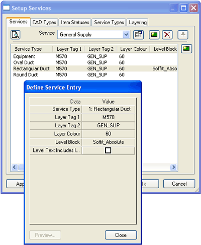
- Select the correct Service from the Service drop-down menu; for example, HVAC - General Supply.
- Select the correct Service Type and assign the Block Definition created earlier, as shown below:
- Click Close.
- Click Apply/OK to close the Setup Services dialog.
Add the Block Levels Label
To add the block levels label:
- Add a rectangular duct item to the drawing.
- Click the Levels button
.
- Select the rectangular duct item.
Create Attribute Definitions
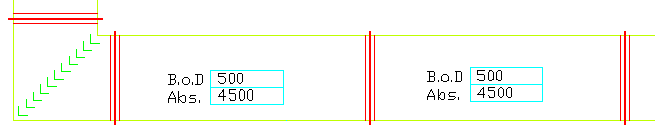
The following pipework example reports levels from an elevation datum (finished floor level) to center line.
- Type ATTDEF, or click
in the CADmep toolbar.
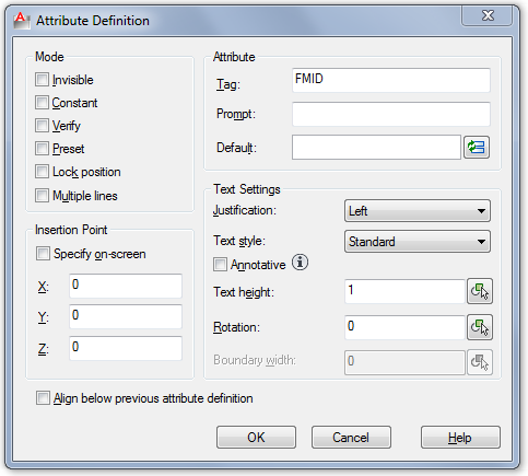
- Type FMID as the first Attribute Tag.
- Check that the Text Style height is set to a value of 1.
- Click OK to add the Attribute Definition to the drawing. (If this is not specified, it is located at 0,0,0).
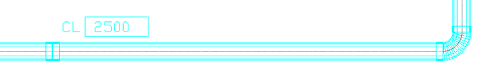
- Create ACAD Text for the Level description, as per the example below "CL". If desired, create a Levels value box.
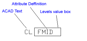
- Use the BLOCK command to create a Block Definition, and select the ACAD Text, Attribute Definition & Level value box.
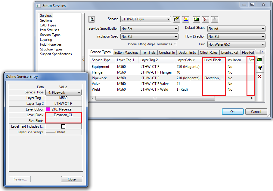
- Enter a Block Definition Name; for example, Elevation_CL
- Click OK to the Block definition dialog.
Note: When setting Soffit or Elevation datum's, see Sections.
Assign the Block Definition to the Service Type
To assign the block definition service type:
- Select the correct Service from drop-down menu; for example, Water & Liquid Supplies - Mains Cold Water.
- Select the correct Service Type and assign the Block Definition created earlier, as show below:
- Click Close.
- Click Apply/OK to the Setup Services dialog.
Add the Block Level Label
- Add a pipework item to the drawing.
- Click the Levels button
 .
.
- Click the pipework item.
Example - Steel work - Levels from Absolute to Top of Steel work
Create Attribute Definitions
The following steelwork example uses levels from absolute to top of the steelwork.
- Type ATTDEF, or click
in the CADmep toolbar.
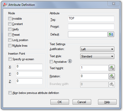
- Type TOP as the Attribute Tag.
- Check that the Text Style height is set to a value of 1.
- Click OK to add the Attribute Definition to the drawing. (If this is not specified, it is located at 0,0,0).
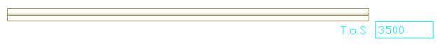
- Create ACAD Text for the Level description, as per the example below "T.o.S" - if desired create a Levels value box.
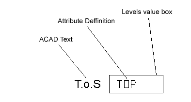
- Use the BLOCK command to create a Block Definition, and select the ACAD Text, Attribute Definition & Level value box.
- Enter a Block Definition Name e.g. "Top of Steel".
- Click OK to the Block definition dialog.
- Click OK to the Edit Attributes dialog.
Note: When setting Soffit or Elevation datum's, see Sections.
Assign the Block Definition to the Service Type
To assign the block definition to the service type:
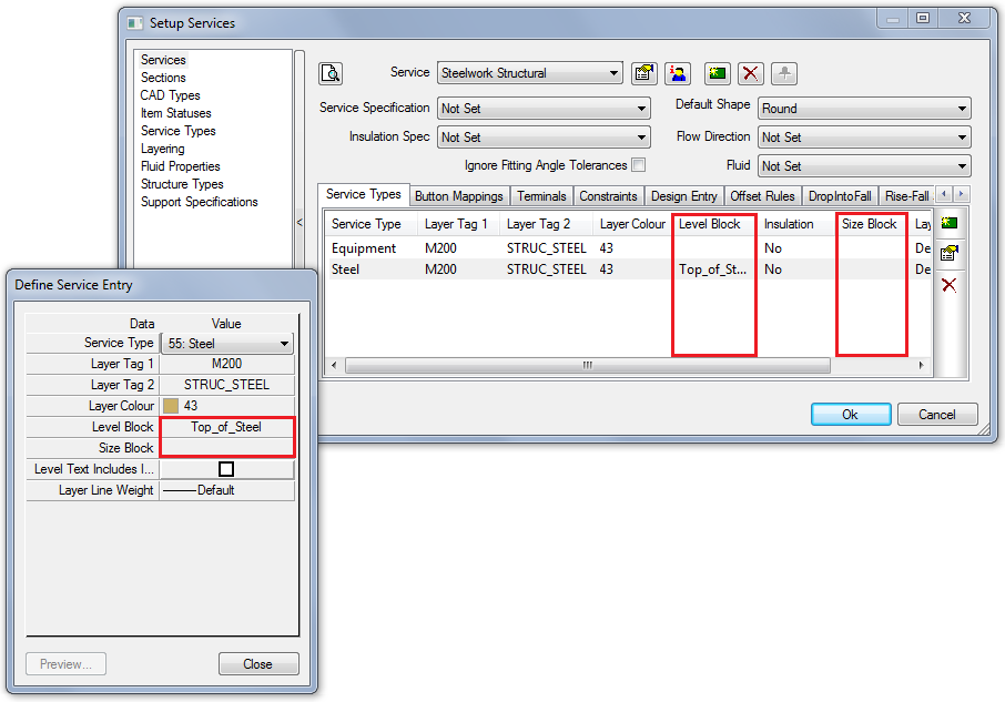
- Select the correct Service from drop-down menu; for example, Structural - Steelwork Structural
- Select the correct Service Type and assign the Block Definition created earlier, as shown below:
- Click Close.
- Click Apply/OK to the Setup Services dialog.
Add the Block Level Label
To add the block level label:
- Add a Structural Steel Item to the drawing.
- Click the Levels button
.
- Click the Structural Steel Item.