In CADmep, access the Drainage Tool dialog by clicking  Design Line, and then on the Service pallet, click Line tab
  Drainage Tool. The Drainage dialog displays.
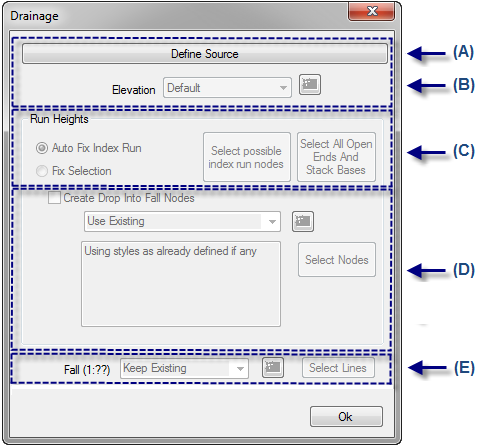
The options available on the Drainage dialog are described below.
Define Source: Clicking this button prompts you to "Select Design Nodes". In the model, click the source node location where the flow of fall will be directed to. A calculate will automatically update the arrow indicators for the fall of flow direction.
Elevation: Specifies the elevation level of the drainage system co-ordinated throughout the building. This can be edited if the system needs re-co-ordinating. New levels can be implemented as required using the Drainage Tool - Add New Elevation. Typically the drainage tool will always set the Elevation to "Default" indicating that the Design Line is utilizing the original level when previously co-ordinating the drainage system throughout the building.
Run Heights: Within a drainage system, fixed items / nodes need to be set to maintain specific run height with a system. Various selection options are available. You can automatically or manually fix for coordination purposes. Within the logic of the tool, various design selections can be executed. For more information, see Drainage Tool - Run Heights.
Create Drop Into Fall Nodes
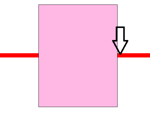
Set Pinch Point: Clicking this button prompts you to select a pinch point position on the Design Line. In the model, click the desired position to specify a pinch point location, then specify the elevation that point should be below. A pinch point is a limiting point for the system to be pushed up to the soffit. The system cannot be moved up beyond this point. Once specified, the pinch point value is displayed on the Drainage dialog, on the Pinch Point button.
The following conceptual diagram represents a pinch point location on a Design Line in plan view. The pinch point position is set on the Design Line on the upstream edge of the limiting object; for example, in some cases the limiting object may be a soffit.
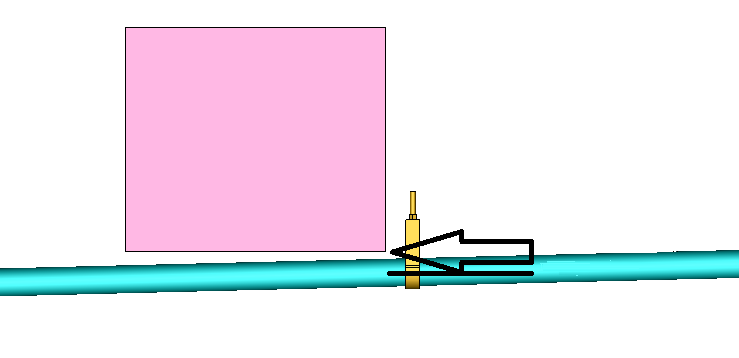
The following conceptual diagram represents an end view, showing the pinch point elevation. Note that in reality, the elevation should allow for the pipe radius.
Fall (1:??): Determines the Fall globally applied within the public health system run. Alternatively, individual Design Lines contained within the system can be configured individually with the Select Lines command.
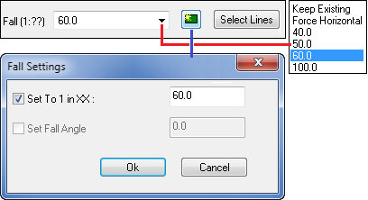
 Add New Fall command.