Manual nesting can be used to completely nest all parts, or to adjust and modify an automatically nested job prior to writing NC. The Manual Nesting feature gives total control over the way parts are arranged on the sheet material. It also includes profiling options that can be applied to an entire sheet, rather than just to individual parts.
To use Manual Nesting:
- When a job is ready to be nested, click Utilities
 Manual Nest, or click the Manual Nest icon from the Utility Bar.
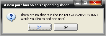
This dialog displays each time a new material and gauge combination is encountered.
- Click Yes to add a new sheet for that particular material and gauge.
Note: If the General Nesting tab has been set to Use Default Sheets, an empty sheet is added automatically. This sheet will be the same size as the default sheet size set in File Setup
Main Database
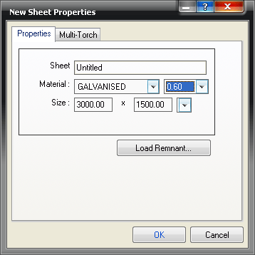
Materials. If the General Nesting has been set to Prompt For New Sheet Size, the following dialog lets the user select the sheet size to be used.
The Manual Nest dialog, similar to what is shown below, displays. This dialog includes four main components: Parts, Sheet Control Centre, Sheet Display and Menus & Shortcut Keys.
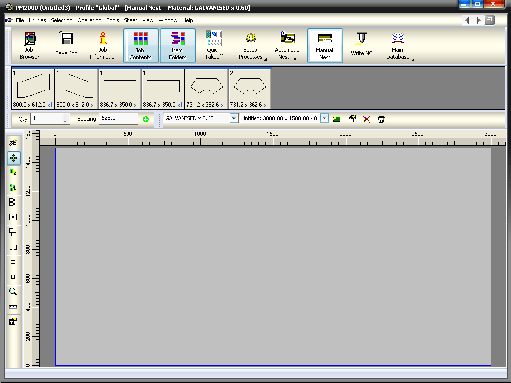
Parts: The top section of the Manual Nest dialog displays the parts that are to be nested on the material and gauge displayed in the sheet control centre.
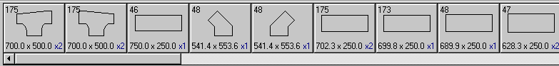
The number in the top left corner of each part is the part number. The number below the part is the blank size (smallest bounding rectangle) and the blue number in the bottom right corner is the quantity of that particular part left to nest.
Before the part has been nested on a sheet, it is displayed as below.

When a part is nested onto the sheet, the display changes to reflect this.

The quantity has been adjusted and a blue cross indicates that no more developments of this part are available to nest.
Only Show Remaining Parts
Within Manual Nest, click View
Only Show Remaining Parts. When this option is selected, rather than placing a cross through the part, it will be removed from the Parts sections altogether, therefore only showing the remaining parts.
Right-click Menu
It is also possible to right-click on any of the parts to display the following menu.
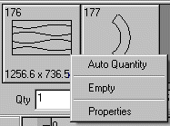
- Auto Quantity: This option is only available on standard parts and profiled parts. It means that an unspecified quantity can be nested, therefore it is primarily used to fill up the remainder of a sheet. It is particularly useful when combined with the fill command explained below.
- Empty: This option removes a part from the parts menu. This can be used if a development of a part is not needed. For example, if only the two cheeks of a square bend were required, the wrappers could be set to empty.
- Properties: This option can be used to display the properties of the item from which the development originated. This is useful for identifying parts, and also gives access to graining options for a part. The part quantity can also be adjusted here.
Sheet Control Centre Toolbar
The Sheet Control Centre toolbar can be either docked, or floating. It can also be toggled on (displayed) and off (hidden) by clicking View
Toolbars
Sheet Control Centre.
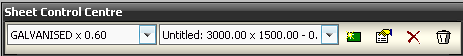
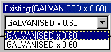
Material and Gauge: The drop-down menu on the left displays the material and gauge currently being nested. To change this, click on the drop-down menu and it will display all of the material and gauge combinations used in the job.
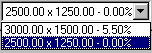
Sheets: The central drop-down menu displays all of the sheets created for a particular material and gauge combination. It displays the sheet size and the percentage of the sheet currently being used. To change the sheet being displayed, click on the drop-down menu and select a different sheet. The list of sheets will only be those relevant to the material and gauge selected above.
New : Creates a new sheet to the default sheet size. This sheet will be the same material and gauge as that selected above.
Properties
 : Modifies the displayed sheet's size and can be used to set a multiple torch configuration for the displayed sheet only. Changes can only be made to a sheet if it is empty.
Delete
 : Removes all parts currently nested on the displayed sheet. The sheet itself is not deleted.
Trash
 : Deletes the displayed sheet from the job.
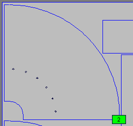
Sheet Display
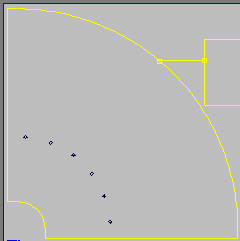
The largest section at the Manual Nesting dialog displays a graphical representation of the sheet to be nested on.
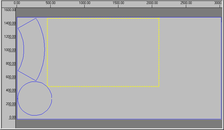
Manual Nesting Dialog Features
- Along the left side and top edges rulers are visible. These can be used to see the size of sheet being worked on.
- Parts with a yellow border are currently selected. The solid line border around the part shows the extents and also indicates that the part is placed on the sheet. Therefore it can only be taken off the sheet again by pressing the Delete key.
- The dotted line shows the part extents plus the minimum margin between parts. This is determined in the General Nesting tab within the Main Database.
- The dashed line also indicates the rotation of the part, if the part is rotated in such a way that it no longer fits on the sheet.
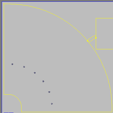
Placing Parts on a Sheet
- To place a part on the sheet, left-click on the relevant part in the Parts section at the top. The part will now be attached to the cursor. Move the cursor down onto the sheet.
- Place the mouse in roughly the correct place and left-click to place a part.
Note: There must be a solid yellow line around the part for it to fit.
- To rotate a part, click and hold the right mouse button and move the mouse in a circular motion. The snap angle of rotation is set to 15 degrees by default. To modify this angle, click Operation
Tool Options, and the following dialog displays.
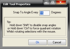
This allows the user to enter a value to define the default snap angle when rotating.
Note: It is also possible to override this setting. Hold the Ctrl key whilst rotating the part to snap to 90 degrees, or hold the Shift key to snap to 1 degree. - Move and rotate operations can be combined to roughly position the part and then rotate it into alignment. To do this, hold both buttons simultaneously and then when the part is rotated, release the right button only; thus still retaining control of the positioning of the part.
Menus and Shortcut Keys
The following menu options are relevant to Manual Nesting only: Selection, Operation, Tools, Sheet and View.
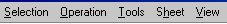
Selection: The selection menu includes certain operations that can also be accessed using the keyboard. The keyboard shortcuts are listed next to the function name. The standard Windows Cut, Copy and Paste commands are available.
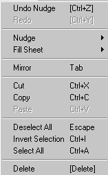
- Nudge / Undo Nudge: Moves parts on a sheet as far as possible is a particular direction: Up, Down, Left and or Right. The keyboard arrow keys also perform this function. It is useful for ensuring that parts are nested as close as possible to each other. Undo Nudge undoes the last nudge performed.
-
Fill Sheet: Places multiple instances of the same part into a nest without having to drag them down from the Parts section independently. The fill will go as far as possible in a direction (Up, Down, Left and or Right) and fills can be combined to quickly fill a sheet. The keyboard arrows combined with the Ctrl key perform the same function.
Note: The Fill Sheet option only uses the amount of parts associated with the selected item.
- Mirror: Flips a part over. This option must be used with caution as the flipped part will be cut with its outer and inner sides reversed when compared to other parts on the sheet. The Tab key also performs this same function.
- Select All, Deselect All and Invert Selection: These options govern which parts are being manipulated. Selected parts will appear in Yellow.
- Delete: The Delete option will remove all of the highlighted or selected items.
Operation: The Operation menu provides access to the following options related to manual nest modes.
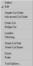
- Select: Click Operation
Select, or click on the Select icon
 . This option allows for parts to be selected or de-selected by left clicking on them, without having to use the Ctrl key. It also allows the user to right-click on a nested part to show the parent item's Properties. While Select is activated, parts on a nest cannot be moved.
Edit: Click Operation
Edit, or click on the Edit icon
 This is the default mode, all operations connected with moving parts, placing parts, flipping parts etc. are performed while in Edit mode.
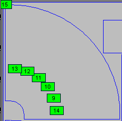
Simple Cut Order: This enables the cut order for the sheet to be altered on a part-by-part basis. To use this option. Click Operation
Simple Cut Order, or select the Simple Cut Order icon
 . Left click on the green squares in the order of the parts to be cut. If the cut order needs to be determined from an existing number onwards, right-click on the number to be the next assigned. This will activate that number as the current one. For example, if 1 - 4 were in the correct order but 5, 6 and 7 needed modifying, right-click the existing number 5, which turns that number yellow, then left click the new number 5 to reassign. Further left clicks will assign 6 and 7.
Advanced Cut Order: Click Operation
Advanced Cut Order, or click on the Advanced Cut Order icon
 . This allows the cut order for the sheet to be altered on a cut-by-cut basis. Each individual cut has a separate number which can be reassigned using the method detailed above.
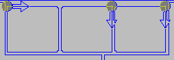
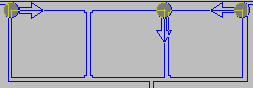
Chain Cut:
 This mode enables parts to be cut in one continuous torch activation, the purpose of which is to minimise pierce points. To place a chain cut, click and drag from one island to another.
Chained cuts will, in general, only cut around half of one part before moving on to the next. The cut will return to finish the part after cutting any parts that are chained to it. The system will try to calculate the optimum cut path based on lead positions and on the parts that are chained or bridged together.
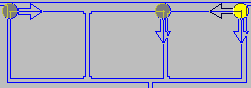
Bridge Cut
 : Similarly to the chain cut option, this also allows for parts to be cut with a continuous torch activation. A bridge cut will cut an entire part before cutting a path to the next part. This characteristic of bridge cuts means that only two parts can be bridged together. To connect more than two parts, a chain cut is used. The main purpose of bridging is that it can be used to terminate the end of a chained run so that the cut can turn around.
Placing bridge cuts works in exactly the same way as chain cuts. Once placed, both can be modified by right- clicking on the small yellow start/end square.
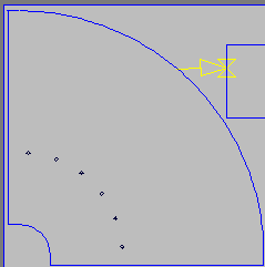
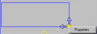
Leadins : This option allows for leads on the nested parts to be re-positioned.
The grey circle indicates the current lead position. To move a lead-in;
- Left-click and hold the mouse on a lead-in.
- Then drag this around the island and the circle will snap to valid positions. On some parts it may only snap to the four corners of a rectangle, for example. This is because the NC code that will be generated will treat each of those four sides as a single instruction, therefore only the corners will be valid lead positions.
Moving the mouse over the lead will display the cut direction indicator (blue) and the alternate cut path indicator (black). It is possible to alter the direction that the part will be cut.
- Move the mouse over the alternate cut path indicator (highlighting the lead in yellow), and left click, the cut direction can be changed.
It is also possible to view and change the lead style applied;
- Right click on the lead position and click Properties to display the Leads dialog. For more information on lead styles, see Tool Use and Leads in the Profiler section.
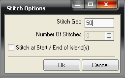
Stitching : This option can be used to stitch parts to the sheet on a part by part basis. To perform this operation, click and drag a selection box around parts to be auto stitched, then right click to display the dialog.
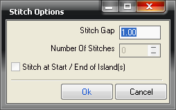
- Stitch Gap: Specifies the length of the stitch.
- Number of Stitches: Specifies the number of stitches required.
- Stitch at Start / End of Island(s): When specified, the cut will leave a gap between the lead in and lead out with the same length as the stitch length value.
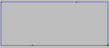
Stitches are shown by black dashes around the island. It is also possible to manually stitch any part.
To set the length of these stitches, click Operation
Tool Options and alter the stitch values there and then click OK.
- To apply the stitches manually, click Operations
Stitching and left click where the stitch needs to be.
Sheet Cut Rail: This option allows the user to place a cut along the rail axis of the machine, select this option.
- Click Operation
Sheet Cut Rail, or click on the Sheet Cut Rail icon

- Then click in the desired position on the sheet.
- To adjust the position, move the cursor over the cut and a white square will appear, left click and hold the mouse, then drag the cut line to the new position.
Sheet Cut Beam: This option works in the same way as the option above, but in the Beam Axis
- Click Operation
Sheet Cut Beam, or click on the Sheet Cut Beam icon

Zoom : This option activates the mouse zoom mode. Left click to zoom in on the cursor position, right-click to zoom out or click and drag a box to zoom on the selected area.
Ruler : The ruler is a rough guide to distances on the sheet. Click Operation
Ruler, or click on the Ruler icon, then click and hold the mouse button to measure between two points. This method of measuring is not accurate in that no definite points can be designated to measure either to or from.
: The ruler is a rough guide to distances on the sheet. Click Operation
Ruler, or click on the Ruler icon, then click and hold the mouse button to measure between two points. This method of measuring is not accurate in that no definite points can be designated to measure either to or from.
Tool Options: The options available here will depend on which mode the operations menu is in. For example, if the Bridge or Chain Cutting is selected, the tool options will allow the user to set the lead in style. If Stitching is selected, the tool options will allow the user to set the length of the stitches.
Tools: The Tools menu offers the user further options.
Select Machine for NC: This option is used to determine which machine to be used when writing the NC code. The * symbol indicates that this is the default machine.
- Click Tools
Select Machine for NC and the following dialog displays.
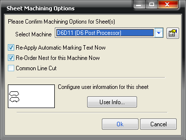
- Re-Apply Automatic Marking Text Now: When selected, it will reposition any marking on parts to fit correctly and be consistent throughout all the parts.
- Re-Order Nest for this Machine Now: Modifies the cut order to the optimum configuration based on Start / Park / Home points.
- User Info: This option is used to configure certain machine-specific parameters, such as Amperage (only available on a few machines).
Outer / Inner / Central: This option highlights the corresponding island types on the nest.
View: The View menu can be used to toggle On/Off display dialogs within manual nesting. It also contains the zoom menu. Zoom commands can also be activated using F3 (Zoom In), F4 (Zoom Out), and F5 (Zoom Extents).