Layer Mapping is used when an item created in AutoCAD is imported as a DXF into the Fabrication products. It allows for the designation of drawn lines to be either cut, marked, drilled, or ignored within the Fabrication products. These layers are first defined in the CAD package before importing as a DXF File.
AutoCAD Layering
Drawings containing parts to be processed often contains many layers. The parts to be processed should therefore be placed on designated layers as appropriate; for example:.
- Parts to be processed with the cutting tool on layer: cutting
- Parts to be processed with the marking tool on layer: marking
- Parts to be processed with the drilling tool on layer: drill
- Text containing attribute information on layers: attributes
The following example uses AutoCAD version 2011. Different versions and other CAD applications may be slightly different; however, the basic principles are similar.
- In AutoCAD open a drawing, then click Layer Properties.
- In the Layer Properties Manager, click New Layer.
- Enter MARKING as the name for this new layer, and change the color to RED (10).
- Click New again, but this time enter OUTERCUT for the name and BLUE (160) as the color.

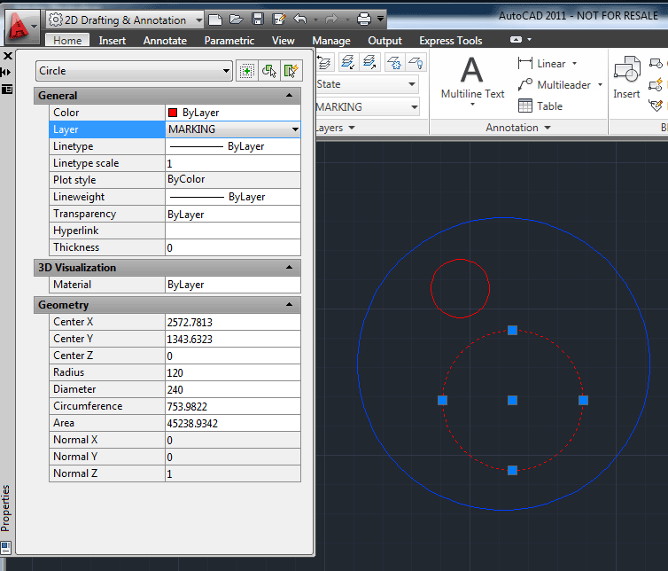
- Click OK to return to the drawing, and click the Properties button to display the properties for the drawing.

- Select an object to change its layer, and in the Properties dialog, change the layer by clicking the down arrow and select OUTERCUT.
- Press the Esc Key, then select a different object and change its layer to MARKING.
Notice how the objects change color to match the different layer colors.
- Click the X in the Properties dialog to close it.
- When finished editing your drawing, click File
 Save As.
- In the files of type section, click the down arrow and select AutoCAD 2000 DXF (*.DXF).
- Name the drawing and then click Save.
Layers
Creates the Layers to be used in the software.
In the example below, 2 layers were created by clicking the New icon
 . The first one is named OUTERCUT and the second layer MARKING to match the names from AutoCAD. Note that layers can be assigned any name required. Colors were also assigned to these layers for use in Opus.
- The imported layer OUTERCUT will be mapped to the layer Default Cutting.
- The imported layer MARKING will be mapped to the layer Default Marking.
The software layer names are arbitrary, and at this stage, do not mean the cutting tool or marking tools will automatically be assigned. Layers must be used in conjunction with Tool / Layer Mapping features.

Tool / Layer Mapping
The AutoCAD layers must now be associated with the layers that are defined in the Autodesk Fabrication product software. This is accomplished on the Layer Mapping dialog.
AutoCAD Layer 0 is usually left blank as this is normally used as the "Canvas" layer.
AutoCAD Layer 1, which in this example was renamed to OUTERCUT, gets assigned to the Autodesk Fabrication product (MAP) Layer named OUTERCUT. The options are then available to either Process, Display Only, or Ignore this layer within the Autodesk Fabrication product software.
AutoCAD Layer 2 which in this example was renamed to MARKING gets assigned to the Autodesk Fabrication product (MAP) Layer MARKING. The options are then available to either Process, Display Only, or Ignore this layer within the software.

Example DXF Import
Parts can be imported directly into an open job, or alternatively, they can be imported into the Item Folders for permanent storage and future use.
Import to Item Folders
To import to item folders:
- From Utilities
Item Folders, and select or create the required folder.
- Right-click in the folder and select New
Import.
Import into a Job
To import into a job:
- Select Files
Import
Items.

- Set the of Type drop-down list to AutoCAD DXF (*. DXF).
- Browse to the required folder.
- Select the Separate Items option if the DXF file contains multiple parts.
- Click Open.

If the AutoCAD filter has been applied before exporting the DXF file, it will not contain any irrelevant layers or drawing elements. However; unwanted layers can be switched off here if necessary. The part will be processed and added to either the item folder or the job.
- To verify the attributes and tools have been assigned correctly, from an item folder, right-click on the parts in the folder and then click Edit to verify in profiler. From a job, right-click on the part and then click on Edit Developments to verify in profiler.