Kerf is the allowance required to compensate for the tool width. With thermal cutting tools, the Kerf Value is normally material and gauge dependent. For example, if the Kerf Value = 1.0, and you need a part 100 x 100, then the cutting program compensates and cuts along a center line at 100.5 x 100.5. When cutting a 100 x 100 hole, the center line would be 99.5 x 99.5.
The following diagram illustrates how the Kerf value works.
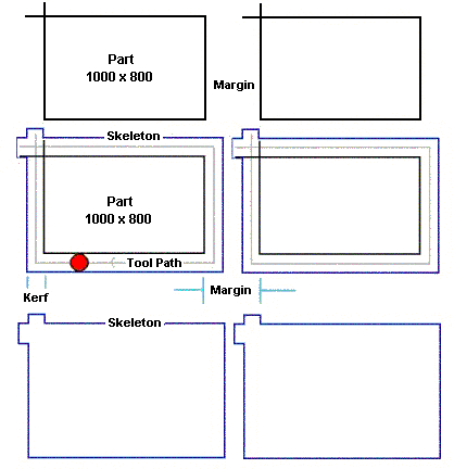
- Two parts, 1000 x 800 are shown nested.
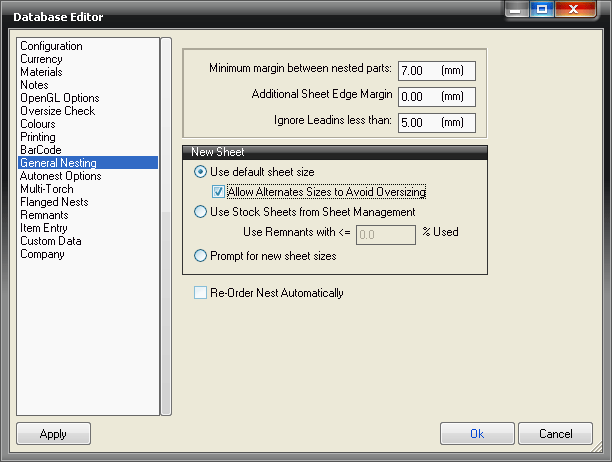
- They will be separated by the margin entered in the general nesting set up, typically 10mm.
- Kerf = Tool Width.
- Kerf can be applied by the software or by the machine controller.
- The end result is that the tool is offset automatically by ½ the Kerf.
- The grey line (center line) shows the tool path around the outside of the parts.
- The default cutting mode is "Kerf left" which means that the kerf value is offset to the left of the cut direction - i.e. outside cuts go clockwise and inside cuts counter clockwise.
- This can be changed in profiler or from manual nesting if required.
- If you measure the skeleton left in the plate this will be = part size + 2 x kerf.
- The margin set up for nesting should be at least 2 x kerf + the required strip necessary to minimize distortion.
- Lead ins/outs should be less than margin-kerf.
- For Oxy-fuel cutting, larger margins are usually required the thicker the sheet.
Setting Up Different Margins
The only way to achieve this with a job that contains multiple thicknesses is to do the following:
- Copy the job 3 times, and delete parts, so that each job contains only one thickness; for example, 10mm, 15mm, 25mm.
- Set up 3 different processes.
The Process option allows different batch processes to be set up.
For example, different processes could be set for 10, 15 and 25mm plate.
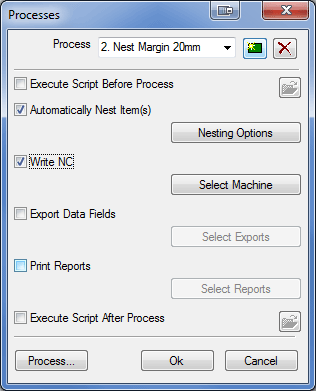
- Change the nest options in each process to have a different margin.
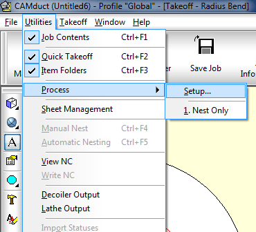
- Click New to create a new Process, and give it a name to identify what it does. In the following example, the new process is named " 2. Nest Margin 20mm".
-
The Additional Sheet Edge Margin option allows for the sheet being slightly misaligned on the machine.
Kerf Compensated by the Controller
Historically, kerf was always calculated by the machine controller software. If this is so, the kerf commands are added in the correct places in the NC data produced. Then, at cut time, the controller asks the user for the kerf value and re-calculates the kerf offset.
Kerf compensated on the Machine Editor dialog
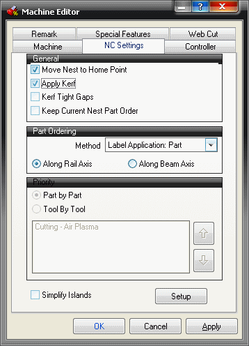

In CAMduct, you can add kerf values directly by doing the following:
-
Click File
 Set up
 Installed Machines
  select the desired machine
  Setup.
 -
On the Machine Editor dialog, click the tab for the type of material (for example, click the Linear Duct tab or the Pipework tab).
- Enter a value for the Kerf field, and then click OK.
In this case you should enter Kerf=0 at the Controller.
In CAMduct, the correct kerf values should be set up in the Machine Tool Database for each material and thickness.
-
To get to the machine tool database, click Tools, select the required tool, and then click Setup
-
You may need to move " Kerf Value" from the Global tab to the Details tab. Click Details, select " Kerf Value" from the drop-down box and then select the Destination. In this case " Details"
-
You now need to enter some figures to define Kerf, for example if the tool width, or kerf value for a given material/gauge = 2mm, enter 2mm in the material database.
- The program will then offset the cutting path by 1mm. The direction of the offset depends on if the contour being cut is an inside hole or the outside of the part.
- You can confirm if kerf is being applied by the software from the View-NC menu option. If kerf is being applied the NC data will be shown in the center line color (magenta) otherwise it will normally show in blue and red.
- When investigating the accuracy of cut parts it is important to de-couple the effects of XY length errors from kerf errors.