In CADmep, you can use Rise and Fall Symbols to draw rectangular and round rise and fall symbols automatically on bends and sectioned straights in Model Space, Paper Space, or only in Sectional views.
The Rise and Fall Symbols options are specified in the database as follows:
- Click
 Edit Main Database
 Takeoff tab
CAD Settings
Display tab.
Takeoff tab
CAD Settings
Display tab.
The CADmep settings should now be visible.
- In the Rise - Fall Symbols section, check the available options to show the Rise - Fall symbols in Model Space, Paper Space and Clipped Views.
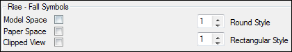
For more information on these settings, see the description of Display tab settings in CAD Settings.
Override Option for Rise - Fall Symbols For Each Individual Service
To override Rise - Fall symbols for an individual service:
- Click Edit Service Database.
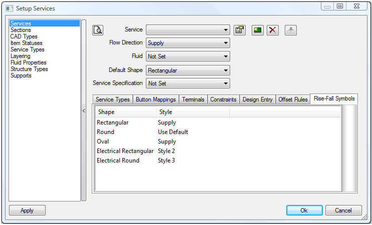
The CADmep Setup Services dialog displays.
- Click the Rise-Fall Symbols tab.
-
To customise the Service with a specific Rise-Fall symbol, the Style options must be selected and changed to suit a specific symbol. Refer to the previous sections illustrating all the symbol styles available for Duct Ventilation, Mechanical Pipe, and & Electrical. For more information, see the description of Display tab settings in CAD Settings.
The options available are:- Rectangular: Use Default, None, Style 1, Style 2, Supply, Extract, Exhaust
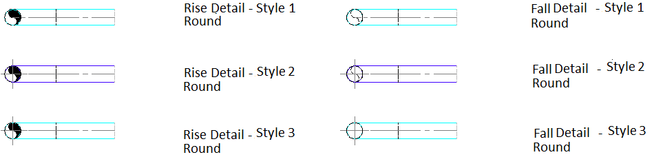
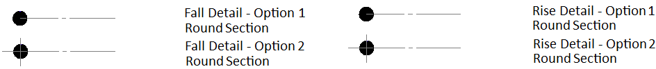
- Round: Use Default, None, Style 1, Style 2, Supply, Extract, Exhaust
- Oval: None, Style 1,Supply, Extract, Exhaust
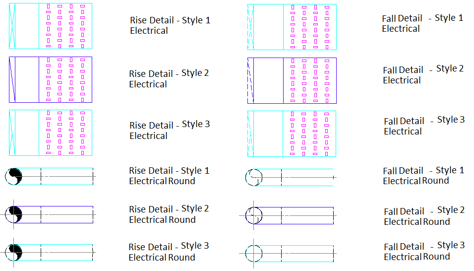
- Electrical Rectangular: None, Style 1, Style 2, Style 3
- Electrical Round: None, Style 1, Style 2, Style 3
The Use Default option uses the settings enabled within the
 Main Database Rise & Fall Symbol settings.
The None option will not apply a Rise & Fall Symbol to that particular Shape / Service.
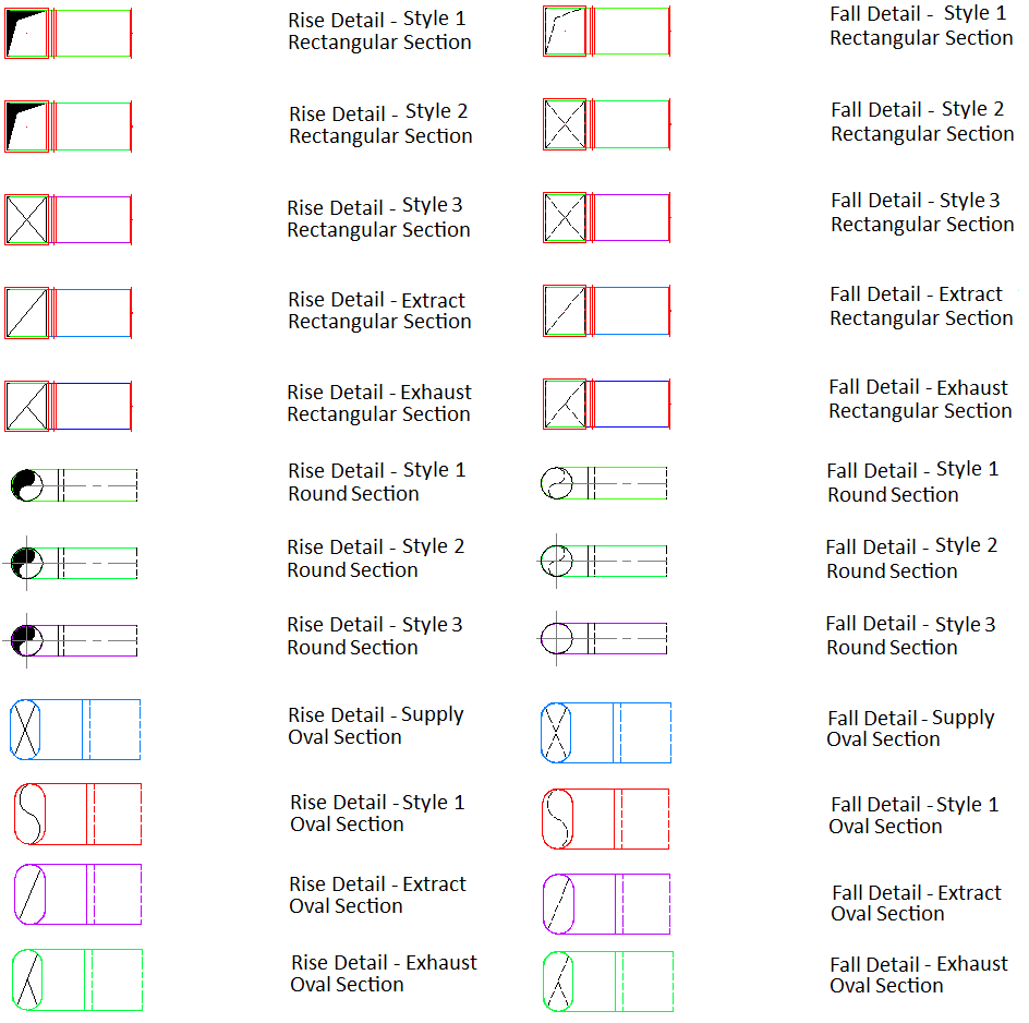
Duct Ventilation
The available Styles are as follows:
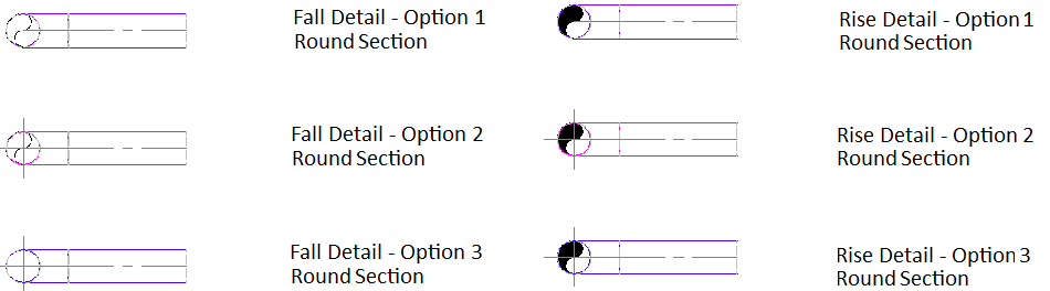
Mechanical Pipe
The available Styles are as follows:
Electrical
The available Styles are as follows :
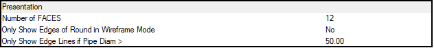
Only Show Edge Lines On
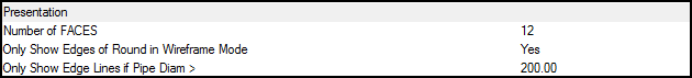
 Only Show Edge Lines > 50.0 Dia
Overriding and Enforcing Rise-Fall Symbols on Objects in a Model
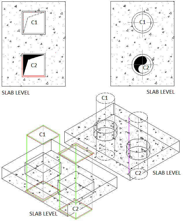
The following example illustrates a duct ventilation rectangular and spiral straight item passing through a structural slab level.
- Select the CADmep straight for the object to become active.
- Right click
Rise-Fall Symbols > C1 End or C2 End.
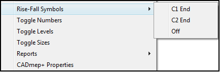
- To enable either End Connector (C1) or End Connector (C2), select C1 End or C2 End as required. The above example shows a duct ventilation rectangular and spiral straight item passing through a structural slab level end connector locations of C1 and C2.
- To turn off the Rise and Fall Symbol, select Off.
Turning Rise & Fall Symbols On and Off within Paper Space View Ports
Turning off the Rise - Fall Symbol on a object:
- Ensure you have an active viewport within Paper Space.
- At the command line, type HIDERISEFALLVP.
- Select the object with the Rise - Fall Symbol applied, and the press Enter to finalise the command.
Turning on the Rise - Fall Symbol on a object:
- Ensure you have an active viewport within Paper Space.
- At the command line, type SHOWRISEFALLVP.
- Select the object with the Rise - Fall Symbol applied, and the press Enter to finalise the command.