The Edge Nesting option allows parts that have one blank size dimension that is equal to the sheet's width to be nested. This is particularly useful for cutting notches on straights ducts (Pattern 1) or any other part that has one blank size dimension that is equal to the sheet's width.
Enable Edge Nesting
To enable the edge nesting option:
- Click
 File
File
 Setup
Setup
 Main Database or click the Main Database icon from the Utility Bar.
- Click on the Autonest Options, and enable the Edge nest parts equal to sheets width option.
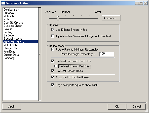
- Click OK and Edge Nesting is enabled.
Note: There is also an Edge Nesting option in the Method tab when Automatic Nesting is selected. It is important that this is not confused with the Edge Nesting described above. If this option is selected, Edge Nesting will be the default nesting method for all parts.
Set Up a Default Lead Style for Edge Nesting
Before using Edge Nesting it is necessary to create a standard lead-out that will be applied to each 'Edge Nested' cut.
Create a Custom Lead
To create a custom lead:
- Click File
 Setup
Setup
 Profile Database or select the Profile Database icon from the Utility Bar.
- Click on the Custom Leads tab.
- Click on the New icon
 .
.
- In the text box, replace Untitled with Edge.
- Ensure that Lead Out is enabled in the View section.
- Click on the Line icon
 . This will enable two more fields. In the Size field type in 5 and in the Angle In field type 45.
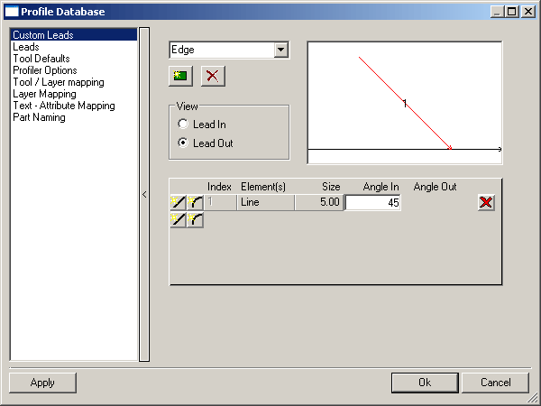
Define a Lead Style for Edge Nesting
To define a lead style for edge nesting:
- Click File
 Setup
Setup
 Profile Database and click on the Leads tab.
- In the Lead Style field click
 and in the Lead Style text box replace the word Untitled with Edge Nest.
- In the Outer Lead section, from the Lead In and Lead Out drop-down menu's, select Edge.
- In the Hole Lead and Central sections ensure that all drop-down menus are set to None.
- Click Apply a new Lead In / Lead Out Style has now been set up.
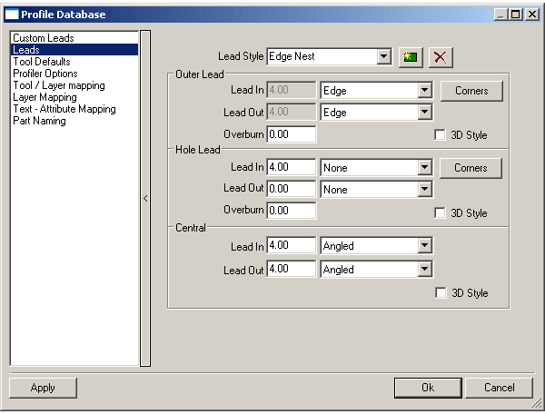
Apply the Edge Lead Style to Edge Lead Style in Tool Defaults
To apply the lead edge style to edge lead style in Tool Defaults:
- Click File
 Setup
Setup
 Profile Database or select the Profile Database icon from the Utility Bar.
- Click on the Tool Defaults tab.
- Locate the Tool Defaults section and in the Edge Lead Style field, from the drop - down menu, select text Edge Nest.
- Click Apply and the Edge Nest Lead In / Lead Out will now be applied to all appropriate cuts by default.
How to use Edge Nesting
When the instructions above have been completed, it is possible to start producing parts using Edge Nesting. The following example demonstrates how Edge Nesting will be applied when a piece of straight duct is added which notches at either end.
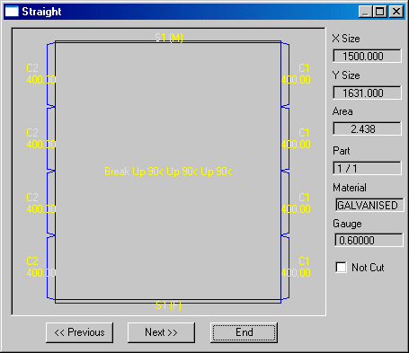
When this part is nested and the NC written, it is possible to view the NC data by doing the following:
- In Job Contents, click on the Nests tab.
- Right-click on the relevant sheet and select View NC.
- From the menu, select a relevant machine and the following dialog displays.
The running order of the plate can be viewed by using the control buttons.
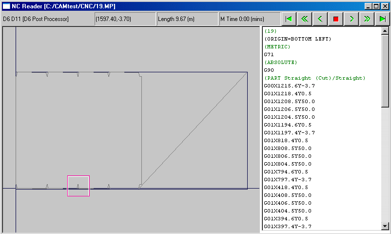
- Zoom in on a certain section of the sheet by left-clicking the mouse in the relevant area, or by positioning the mouse over a relevant area and pressing F3.
- Zoom out by left-clicking with the mouse, or by pressing F4.
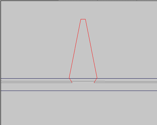
- Zoom in on one of the notches as marked above. In this view, the notch is clearly visible, complete with the Edge Nest Lead In / Lead Out.
 Note: All parts that are exactly the same as the defaults sheet width will be edge nested.