Custom leads are used to create lead styles that are composed of more than one element. As shown in the example below, the lead might have to be custom if the complexity of the part demands that the lead in or lead out avoids some other area on the part. Custom leads can also be used to improve overall cut quality or can be used as a 'key locking' device to minimize plate distortion.
To access the Custom Leads options, click File
 Setup
Database
Manufacturing, and select the Custom Leads in the left pane, under Tool Defaults.
Setup
Database
Manufacturing, and select the Custom Leads in the left pane, under Tool Defaults.

The Custom Leads options are described below:
New: Click
 to create a new custom lead. Enter a name for the new lead in the text box.
Delete: Click
 to delete the currently selected custom lead.
View: The View options (Lead In or Lead Out) changes the way the lead is seen. The lead can still be assigned to a lead In or out independently of this switch.
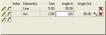
Custom leads are defined by a series of line and arc segments. The line elements are defined by specifying a size and angle for the lead. Arc elements are defined by specifying a size (radius) and the start / end angles of the arc.

The length of the lead section is set here. Each section can be set to a different length.
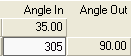
The angle always works with zero pointing to the right. To change from clockwise to counter-clockwise, use the
 icon. The
icon deletes the selected lead section.
icon. The
icon deletes the selected lead section.