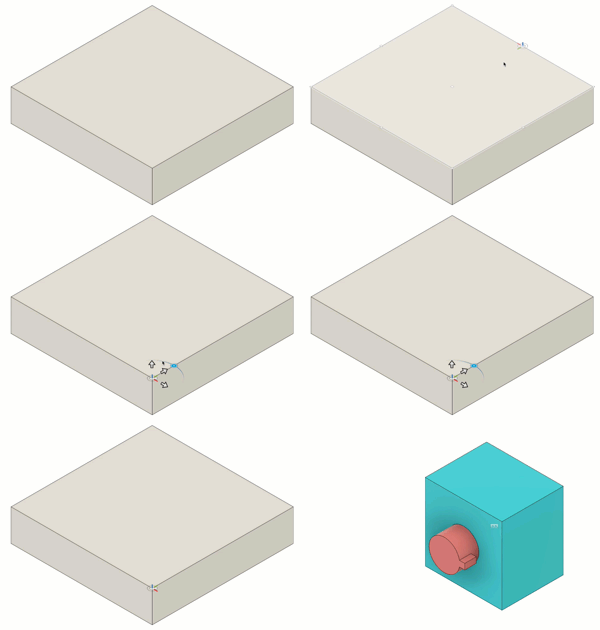
Create an as-built joint
Learn how to use the As-Built Joint command to create a joint between components that are already positioned in relation to each another in Fusion.
On the toolbar, click Design > Solid > Assemble > As-Built Joint
 .
.The As-Built Joint dialog displays.
Select two components to join.
For any Joint Type except Rigid
 , select a Mode, then adjust its associated settings to place the joint origin:
- Simple
 : Select a Snap point to place the joint origin.
 - Between Two Faces
 : Select Plane 1 and Plane 2 to center the joint origin between them, then select a Snap point.
 - Two Edge Intersection
 : Select Edge 1 and a non-parallel Edge 2 to locate the joint origin at the extended intersection.
- Simple
In the Motion section, select the Joint Type, then adjust its associated settings:
- Rigid
 : Lock components together.
 - Revolute
 : Rotates a component around the joint origin.
- Rotate: Choose the axis to rotate around.
- Slider
 : Slides a component along a single axis.
- Slide: Choose the axis to move along.
- Cylindrical
 : Rotates and slides a component on a single axis.
- Axis: Choose the axis to rotate around and move along.
- Pin-Slot
 : Rotates and slides a component on two different axes.
- Rotate: Choose the axis to rotate around.
- Slide: Choose the axis to move along.
- Planar
 : Rotates a component around one axis normal to a plane and slides it along two axes parallel to the plane.
- Normal: Choose the axis normal to the plane.
- Slide: Choose the axis to move along.
- Ball
 : Rotates a component around all three axes on a gimbal system (three nested rotations).
- Pitch: Choose the lateral axis.
- Yaw: Choose the perpendicular axis.
- Rigid
Optional: In the Joint Motion Limits section, define and limit the range of motion for the joint:
- Motion: Select the degree of motion to set limits for. This is available when you have selected a Joint Type that has more than one degree of motion.
- Minimum: Specify the minimum limit on the range of motion.
- Maximum: Specify the maximum limit on the range of motion.
- Rest: Specify the resting position for components within the range of motion.
Click Preview Motion to preview the joint animation.
Click OK.
The joint displays in the canvas and in the Joints folder in the Browser.
Tips
Since components are already in position, you can select them in any order.
In the Browser, expand the Joints folder, right-click a Joint, then click Animate Joint to animate it from outside the dialog.
Hover over a face, then hold
Ctrl(Windows) orCommand(MacOS) to snap to points on that face.
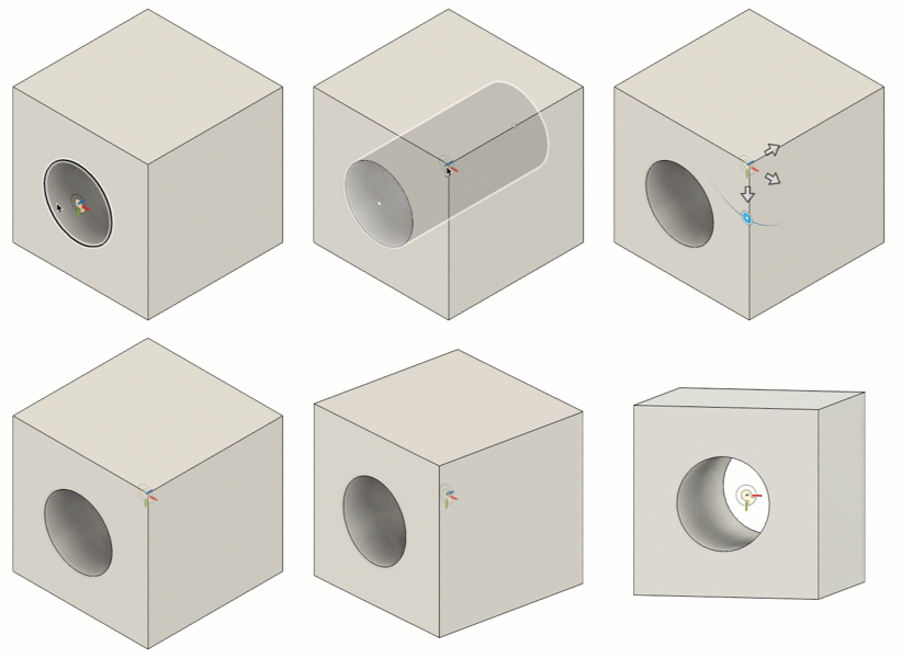
If snap points along the axis of a hole are obscured by other features, hover over the hole, hold
Ctrl(Windows) orCommand(MacOS), then click a snap point.