Create associative references in an assembly
Learn how to use the Reference Objects tool to create explicit associative references between an external component and other design features in an assembly in Fusion.
Create associative references
Open an assembly that contains external components.
In the Browser, click Edit In Place
 next to an external component.
Expand the Edit In Place menu at the top of the canvas.
Select Reference Objects.
The Reference Objects dialog displays.
In the Browser or the canvas, select the design features you want to reference in the assembly:
Components
Bodies
Sketches
Construction geometry
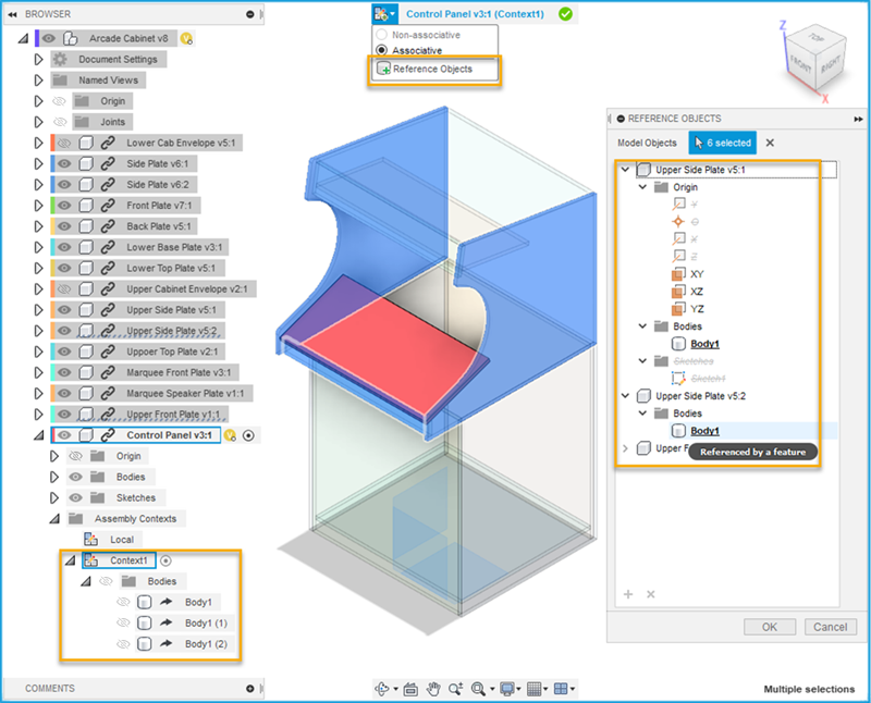
Optional: In the dialog, select objects, folders, or components, then click the
Xbutton to exclude them.Click OK.
In the Browser, the design features you selected are derived into an Assembly Context.
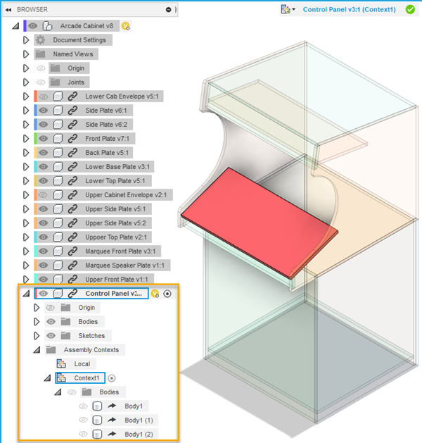
On the Edit In Place menu, click Finish Edit In Place
 to return to the parent design.
Save the assembly.
Right-click the external component.
Select Open to open the design in its own document tab.
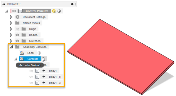
In the Browser, expand the Assembly Contexts folder.
Next to the Assembly Context, click the Activate Context radio button to activate it.
The design features you referenced with the Reference Objects tool display in-context. Their opacity is reduced. You can reference any of the design features as you work on the external component.
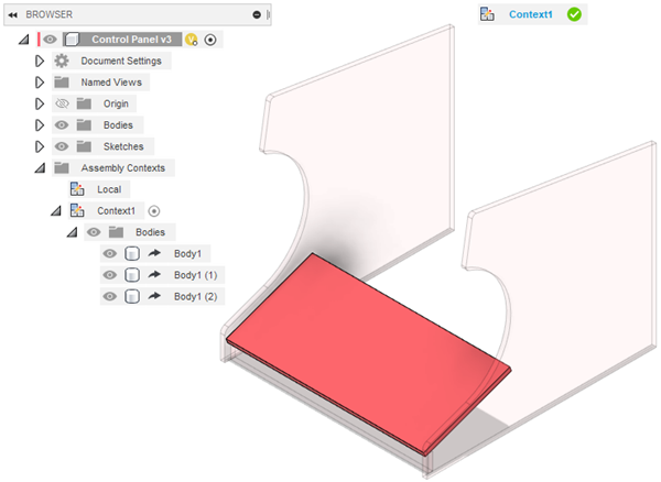
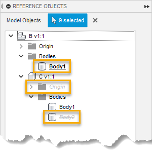
When you create an associative relationship between geometry in the external component and a referenced design feature, the object displays bold and underlined in the Reference Objects dialog. When you exclude a design feature, the object displays in grey strikethrough.
When referenced design features change in the assembly, the changes are reflected in the external component when you update the assembly and sync any out-of-date assembly contexts. Any associative relationships that you create between geometry in the external component and referenced design features in the assembly will also update to reflect changes.