Edit In Place
In Fusion, Edit In Place lets you activate and edit an external component in the context of the assembly without leaving the parent design.
When you activate Edit In Place, you can see the component in its real location within the assembly as you edit it.
Edit In Place makes it easier to take a top-down design approach, because you can edit external components within the context of the parent design.
When you activate Edit In Place for an external component:
- The external component displays in the canvas.
- Other components in the parent design become inactive. You cannot edit them, but they remain visible in the canvas to provide you with the full context of the design.
- You can measure relative distances or create associative relationships between the geometry of the external component and the inactive components.
After you End Edit In Place ![]() , if you change the size or position of the referenced components, the component you just edited updates as well.
, if you change the size or position of the referenced components, the component you just edited updates as well.
Environment overview
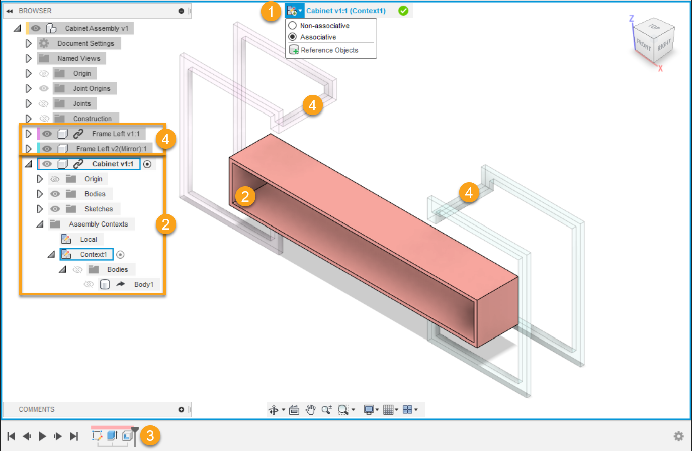
- Edit In Place menu and border:
- The menu displays at the top of the canvas.
- Non-Associative
 : Only allows local edits. Does not create associative references between this external component and other components in the assembly.
 - Associative
 : Creates associative references between this external component and other components in the assembly.
 - Reference Objects
 : Creates associative references between the current design and other components, bodies, sketches, and construction geometry.
 - Visibility Control
 : Controls the visibility and appearance of components during Edit In Place to improve clarity in complex designs. Settings persist for the active Edit In Place session and revert when you end it. Fusion remembers your last Edit In Place visibility choices across sessions for quick reuse.
- Non-Associative
- An icon indicates the associativity of the active assembly context.
- The name of the external component that you are editing displays.
- The name of the active assembly context displays in parentheses.
- A blue frame appears around the canvas.
- The menu displays at the top of the canvas.
- Active external component in the browser and canvas:
- The external component that you are editing is highlighted in blue in the browser and displays at full opacity in the canvas.
- The Assembly Contexts folder contains the assembly contexts you create.
- The active assembly context is highlighted in blue.
- The external component’s Timeline displays.
- Other components:
- Other components in the design are inactive.
- Inactive components display at reduced opacity, but you can still select them.
Assembly Contexts
If you reference geometry of parent and sibling components to define the size or shape of the component you are editing, an Assembly Context is created in the parent design.
An Assembly Context is the connection between a parent design and an external component at a specific point in time. It holds positional information related to the assembly. It is where geometry is derived to maintain the association to the parent design.
A complete Assembly Context includes:
An Assembly Context in the Assembly Contexts folder nested under the child external component in the browser.
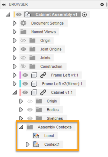
A marker in the Timeline of the parent design.

An Assembly Context is created during Edit In Place when you:
- Associate a dimension with another component
- Associate a constraint with another component
- Associate a sketch projection with another component
- Move a component into place and capture its current position
Features you create while an Assembly Context is active are linked to it. An Assembly Context feature is added to the parent design's Timeline.
When you reference geometry, it is derived into the external component as an Assembly Context. This makes the geometry available to the external component when you open it outside of the assembly. You may want to open the external component in its own tab and activate the Assembly Context if you:
- Have referenced all of the objects you need to reference in order to work outside the context of the assembly.
- Need access to the expanded set of modeling tools beyond what is available inside Edit In Place.
Local context
Each Assembly Contexts folder contains a Local Context.
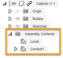
The Local Context represents the external component as the design would appear if you opened it in its own document tab. It maintains its own set of positions for child components.
When you activate the Local Context:
- Geometry in the parent design is hidden and cannot be selected.
- You cannot make any associations to geometry in the parent design.
- Child components in the external component are positioned according to their positions in the external component.
- You can use some tools related to position, joints, and motion that are not available in assembly contexts.
Automatic activation
When you edit a feature that depends on geometry in an Assembly Context, the Assembly Context is automatically activated.
Reference objects
The Reference Objects tool creates explicit associative references between an external component and other design features in an assembly.
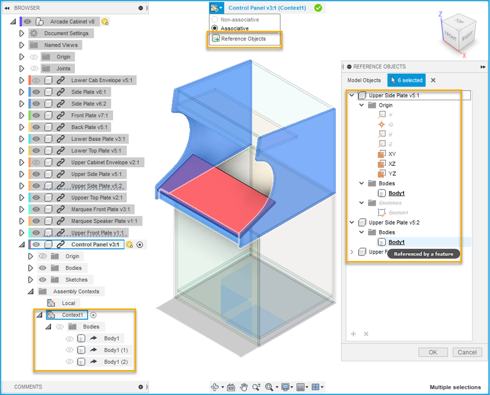
During associative Edit In Place, the Reference Objects tool is available in the Edit In Place menu at the top of the canvas.
You select design features in the Browser or in the canvas. The referenced design features are derived into an Assembly Context.
You can use the Reference Objects tool to explicitly reference objects in an assembly before starting detailed design work. To make detailed design work clearer and easier to perform, reference only the objects in the assembly that are important for a component in context.
 |
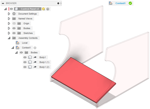 |
| assembly view | activated assembly context with reference objects |