Joint types
Learn about joint types in Fusion.
You can use both the Joint and As-Built Joint tools to create 7 joint types in Fusion. Each joint type uses different degrees of freedom to define motion. You can also add Motion Limits, use Contact Sets, Rigid Groups, and other component relationships in combination with joints to create more realistic movement in your design.
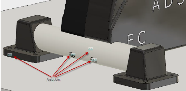
Rigid
| The Rigid Motion allowed: none Rotate: Define the axis around which the component will rotate. Common Uses:
|
 |
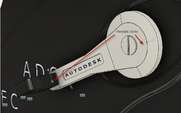
Revolute
| The Revolute Motion allowed: 1 rotation Rotate: Define the axis around which the component will rotate. Common Uses:
|
 |
Slider
| The Motion allowed: 1 translation Slide: Select the axis that the component will move along. Common Uses:
|
 |
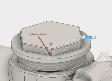
Cylindrical
| The Cylindrical Motion allowed: 1 translation and 1 rotation Axis: Define the axis that the component will move along and rotate around. Common Uses:
|
 |
Pin-Slot
| The Pin-Slot Motion allowed: 1 translation and 1 rotation Rotate: Define the axis that the component will move along. Slide: Define the axis that the component will rotate around. Common Uses:
|
 |
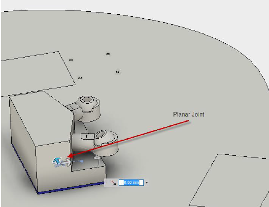
Planar
| The Planar Motion allowed: 1 translation and 1 rotation Normal: Define the axis that the component will rotate around. Slide: Define the axis for planar movement. Common Uses:
|
 |
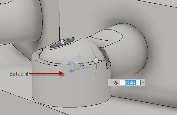
Ball
| The Ball Motion allowed: 1 translation and 1 rotation Pitch: Define the lateral axis that the component will rotate around. Yaw: Define the perpendicular axis that the component will rotate around. Roll: The longitudinal axis for Roll is determined automatically once Pitch and Yaw are defined. Common Uses:
|
 |
Axis definition
- X Axis, Y Axis, and Z Axis let you choose a predefined axis crossing the Joint Origin.
- Custom Axis lets you choose an axis away from the Joint Origin.
Note: When you create a joint, you also create a parameter that you can alter in Parametric Modeling.
Note: When you create a joint, maintaining the fewest degrees of freedom will help you test your assembly faster.