Joint Origin reference
The Joint Origin command positions a joint origin on a component in Fusion. Joint origins define the geometry used to relate a joint's components.
Design > Assemble > Joint Origin ![]()
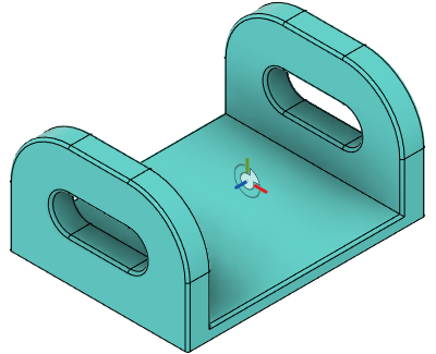
Mode
Select geometry to define the joint origin.
| Joint origin mode | Example |
|---|---|
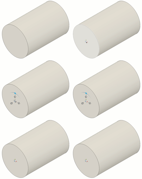 |
|
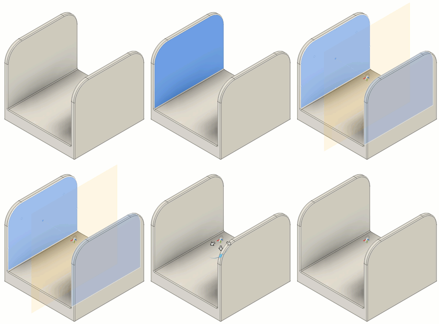 |
|
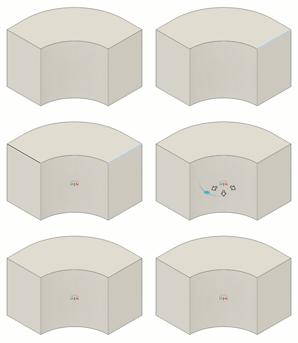 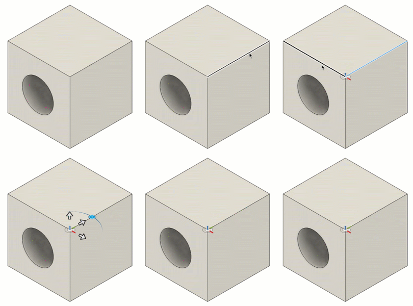 |
Planes, Edges, and Snap
Select the geometry to define the joint and joint origin.
| Option | Action |
|---|---|
| Plane 1 | Select a face |
| Plane 2 | Select a second face |
| Edge 1 | Select an edge |
| Edge 2 | Select a non-parallel edge |
| Snap | Select a snap point to place the joint origin |
Alignment section
Adjust the angle, offsets, and orientation of the joint to align it.
Angle, Offsets, Flip, and Reorient
| Option | Action |
|---|---|
| Angle | Rotates the reference coordinate system of the joint origin to align components when you create a joint |
| Offset X | Offset joint origin along the X axis |
| Offset Y | Offset joint origin along the Y axis |
| Offset Z | Offset joint origin along the Z axis |
| Flip |
Flips the joint origin to align components when you create a joint |
| Reorient | Select two axes to reorient the joint origin |
| Z Axis | Select Z axis |
| X Axis | Select X axis |