Generate a Circular toolpath
On the Manufacture workspace toolbar, click Milling > 2D > Circular.
The Circular dialog opens.
On the Tool tab, click Select to pick a tool. If you have not created a tool to use, in the left panel of the dialog, from the Fusion Library, pick a tool from the Milling Tools (Inch) or the Milling Tools (Metric) library.
Tip: Flat end mills and bull-nose end mills are best suited for the Circular toolpath.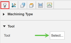
On the Geometry tab within the same dialog, from the Selection Mode drop-down menu, pick Faces.
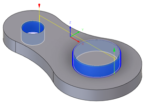
With the Circular Face Selections field active, select cylindrical or conical faces on the model that you want to machine. The toolpath preview appears as you select each face.
On the Passes tab, set the Compensation Type to specify how to adjust for any tool wear.
Tip: Mouse over the Compensation Type parameter drop-down list for more information.Optional steps:
To generate multiple side cuts, enable the Multiple Passes checkbox.
To generate a single pass instead of machining at multiple depths, deselect the Multiple Depths checkbox.
To clear any stock that is left over from tool deflection, enable Repeat Passes to repeat the pass. The repeating pass is commonly referred to as a spring pass.
For safer entry and exit moves on smaller holes, on the Linking tab, in the Leads & Transitions group, enable the Lead to Center checkbox.
Click OK.
The toolpath is generated.
