Generate a 2D Contour toolpath
On the Manufacture workspace toolbar, click Milling > 2D > 2D Contour.
The 2D Contour dialog opens.
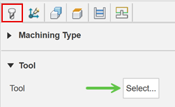
On the Tool tab, click Select to pick a tool. If you have not created a tool to use, In the left panel of the dialog, from the Fusion Library, pick a tool from the Sample Tools library.
Tip: Bull-nosed and flat bottom type end mills are best suited for 2D Contour toolpaths.
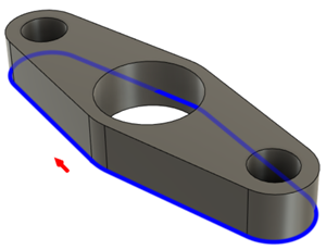
On the Geometry tab, with Contour Selection active, select an edge or a sketch. The contour selection is used to drive the toolpath.
Verify that the red contour arrow is pointing clockwise to machine outside the contour or pointing counterclockwise to machine inside the contour. If necessary, click the contour arrow to flip its direction.
 Tip: Hold Alt and click a contour on the model to select an individual contour. You can access additional contour selection tools by click an existing contour selection with the Contour Selection active:
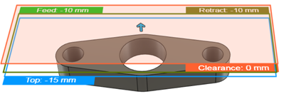
On the Heights tab, adjust the vertical area to machine in Z, by setting the Top Height and Bottom Height of the cutting area. By default, the Bottom Height is set to the Selected contour(s).

On the Passes tab, set the Compensation Type to specify how to adjust for any tool wear.
Tip: Mouse over the Compensation Type parameter drop-down list for more information.Optional steps:
To avoid binding of the tool in tight corners, enter a Minimum Cutting Radius.
To improve precision, enable the Multiple Finishing Passes checkbox. This allows you to take lighter, equally spaced cuts.
To extend the beginning and the end of open contours, try using the Tangential Extension Distance or the Tangential Fragment Extension Distance, located on the Geometry tab and Passes tab respectively.
To reduce the NC program size, enable Smoothing.
Click OK.
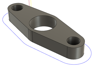
The toolpath is generated.

Contour selections
Watch this video to see how to work with the contour selection tool.