Generate a Morph toolpath
On the Manufacture workspace toolbar, click Milling > 3D > Morph.
The Morph dialog opens.
On the Tool tab, click Select to pick a tool. If you have not created a tool to use, In the left panel of the dialog, from the Fusion Library, pick a tool from the Sample Tools library.
Tip: Bull-nosed and ball type end mills are best suited for the Morph toolpath.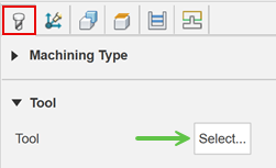
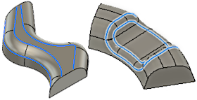
On the Geometry tab, select two or more edges to represents the machining area. These can be open ended or closed chains.
On the Passes tab, enable set the Use Stepover to set the cut spacing per pass. A smaller distance will create a smoother surface finish.
Tip: Disable to specify a fixed Number of Stepovers.Optional steps:
To control the Stepover value automatically based on the desired surface finish, enter a Cusp Height value.
Note: You must have Use Stepover selected to use the Cusp Height parameter.To spread out the cut spacing use the Contour Offset parameter.
For chains with an unequal number of entities, set Morph Mode to Closest.
To cut past the ends of open chains, use the Pass Extension parameter.
To cut beyond the boundary of the select chains, or stay inside of the boundary, use the Number of Offset Stepovers parameter, with a positive or negative value.
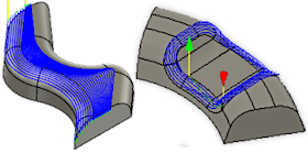
Click OK.
The toolpath is generated.