Generate a Pocket Clearing toolpath
On the Manufacture workspace toolbar, click Milling > 3D > Pocket Clearing.
The Pocket dialog opens.
On the Tool tab, click Select to pick a tool. If you have not created a tool to use, In the left panel of the dialog, from the Fusion Library, pick a tool from the Sample Tools library.
Tip: Bull-nosed and flat end mills are best suited for removing material with a toolpath like Pocket Clearing.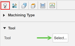
On the Geometry tab, you may contain the toolpath area with a Machining Boundary and then select the face, edge, or sketch that represents the area to be machined. If no selection is made, the entire model will be evaluated for machining within the defined Stock box.
Note: If you select None from the Machining Boundary drop-down list, where possible, the tool leads in from outside of the part to avoid ramping or plunging into the stock.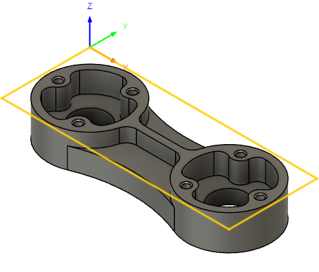
On the Passes tab, enable the Manual Stepover to set the Maximum Stepover side cut amount. Disabled, the stepover value will be 95% of the flat area of the selected tool.
Tip: Consult your tooling supplier for step over recommendations. Typically this will depend on the depth of the cut, material type, tool size and rigidity of the setup.Optional steps:
The Z depth per pass can be adjusted using the Maximum Roughing Stepdown parameter.
To adjust the material for a future finishing operations, enable the Stock to Leave checkbox.
To reduce the NC program size, enable Smoothing.
To adjust the final Z depth, go to the Heights tab and offset the Bottom Height. The Model Bottom is the default final depth.
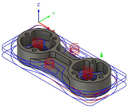
Click OK.
The toolpath is generated.