Generate a Project toolpath
On the Manufacture workspace toolbar, click Milling > 3D > Project.
The Project dialog opens.
On the Tool tab, click Select to pick a tool. If you have not created a tool to use, In the left panel of the dialog, from the Fusion Library, pick a tool from the Milling Tools (Inch) or the Milling Tools (Metric) library.
Tip: Ball-nosed, tapered mill and engrave/chamfer mills are best suited for the Project toolpaths.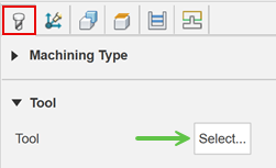
Within the same dialog, go to the Geometry tab. Select the geometry you would like to project. This can be in the form of Sketch geometry prepared ahead of time, but you may also select edges from the model. You can see the selected geometry listed within the Curve Selection field. These curves will be projected down through the current tool plane, onto the the faces of the model below along the Z axis.
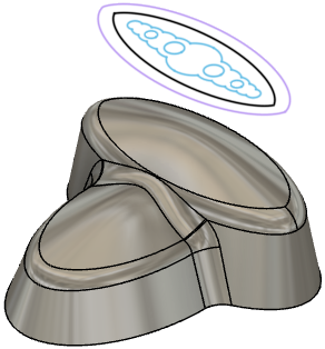
Sketch curves shown above the model.
You may contain the projected toolpath area with a Machining Boundary and then select the edge, or sketch that represents the area to be machined. If no selection is made, the entire model will be evaluated for the projected machining faces.
On the Passes tab, set the Axial Offset to control the final depth of the cut into the model face.
Optional steps:
To change the direction of the cuts, set the Direction parameter.
To machine multiple Z depths, enable the Multiple Depths parameter.
To reduce the NC program size, enable Smoothing.
Click OK.
The toolpath is generated.
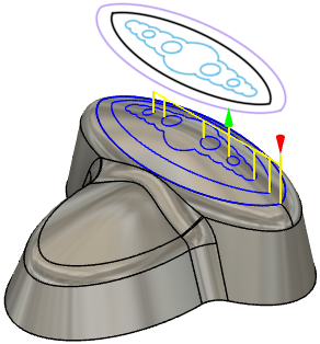
2D sketch curves projected onto the model