Form mill tools
A form mill tool is a specialized cutting tool designed to create complex shapes and contours. These tools are custom designed to match specific shapes or forms required for specialized jobs. While standard milling tools, such as end mills, can produce flat surfaces and 3D shapes, form mill tools are useful for cutting intricate 2D profiles, curves, and cavities. Form mill tools can help reduce cycle time by minimizing the need for tool changes and reducing the number of machining operations required.
To create a form mill tool, you must create a sketch, or upload a CAD drawing, of a closed profile of half the tool. Fusion then revolves the half profile around an axis.
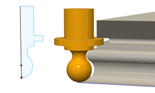
Compensation point
The compensation point is a specific location on the form mill tool that helps it follow the shape you want to cut. It makes sure that the form mill tool is positioned correctly to cut precisely.
 |
 |
 |
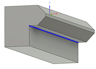
| Compensation point | Contour selection | Resulting toolpath |
You can set the compensation point yourself or let Fusion choose it automatically. If set automatically, the compensation point is placed level with the tip of the tool and aligned with the tool's widest diameter.
If you need to adjust the tool's cutting height, change the Tip Offset when editing the form mill tool in the Tool Library.
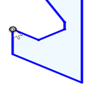
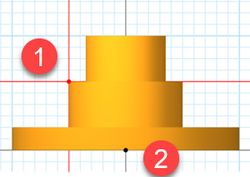 |
1. The red dot represents the compensation point. 2. The black dot represents the point from which the toolpath is driven. It is calculated based on the compensation point and represents the Z offset of the tool. |
Supported strategies
Form mill tools work with most 2D and 3D milling strategies. However, they are not compatible with most multi-axis milling strategies.