Create a form mill tool
Create a sketch or upload a CAD drawing of a closed profile of half the tool you want to create.
On the Manufacture workspace toolbar, on any tab, click Manage > Form Mill
 .
.Next to Tool Profile, ensure Select is active, then, on the canvas, click the closed profile.
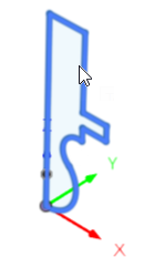
Next to Tool Axis, click Select, then, on the canvas, click the segment of the sketch that you want the profile to be revolved around.
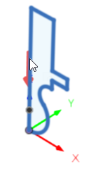
By default, the red arrow on the canvas indicates the Z minus direction. If you need to change the direction to be opposite, select the Flip Axis checkbox.
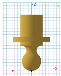
By default, the Compensation Point is automatically placed level with the tip of the tool and aligned with the tool's widest diameter. If you want to change the location, on the canvas, click the desired location on the profile.
Click OK to add the form mill tool to the Documents library in the Tool Library.
Specify the cutting parameters for the form mill tool:
On the Manufacture workspace toolbar, on any tab, click Manage > Tool Library.
Select the Documents library.
Select the newly created form mill tool.
Click Edit Tool.
Complete the settings in the dialog, then click Accept.
You can now select the form mill tool for your operations.