Turning tool reference
General tab settings
| Parameter | Explanation |
|---|---|
| Description | A textual description of the tool. This description is included in the tool name shown throughout CAM. |
| Vendor | The manufacturer or vendor of the tool. Use this to identify the source for purchasing this specific tool. |
| Product id | The vendor's identifier (ID) for the tool. This can be the catalog, model, or part number of this tool. |
| Product Link | The vendor's website or contact information to acquire this tool. This link appears in the Info tab on the tool library. Selecting this link will take you to the suppliers external website. |
Insert tab settings
| Parameter | Explanation |
|---|---|
| ISO Code | If you know the insert tooling code, you can enter it here and to automatically populate other insert settings. Set your Unit to Inch for ANSI codes and Millimeters for ISO codes. Available for Turning General and Turning Boring tool types. |
| Shape | The shape of the insert using the common manufacturer letter designations. |
| Relief Angle | The draft on the faces of the insert that contacts material during machining. Available for Turning General and Turning Boring tool types. |
| Tolerance | An insert tolerance by letter designation, as defined by the tooling manufacturers. |
| Cross Section | The hole and chip breaker shape of the insert. |
| Insert Size | An inscribed circle size by using the numerical designation, as defined by the tooling manufacturers. Available for Turning General and Turning Boring tool types. |
| Thickness | A thickness by using the numerical designation, as defined by the tooling manufacturers. |
| Corner Radius | A corner radius size by using the numerical designation, as defined by the tooling manufacturers. |
| Type | The tool insert type. This changes the settings available to define the insert. |
| Unit | The tool unit of measurement (Millimeters or Inches). |
| Material | The material of the tool. Options include Unspecified, HSS, Ti Coated, Carbide, and Ceramic. |
| Overall Length | The entire length of the insert. Available for Turning Grooving and Turning Threading tool types. |
| Width | The non-cutting width of the tool. Available for Turning Grooving and Turning Threading tool types. |
| Groove Width | The cutting width of the tool. Available for Turning Grooving tool types. |
| Minimum Thread Pitch | The smallest thread pitch that the insert can create. This value depends on the Thread Tip Width or Thread Tip Radius of the insert. They determine how little of the insert to use to create a smaller thread. Available for Turning Threading tool types. |
| Maximum Thread Pitch | The largest thread pitch that the insert can create. This parameter defines the shape of the insert. Available for Turning Threading tool types. |
| Internal Thread | When selected, enables machining of internal threads. Available for Turning Threading tool types. |
| Thread Profile Angle | A value of the angle between two sides of the thread, in degrees. Enter a value less than 90 degrees. Available for Turning Threading tool types. |
| Thread Tip Type | A flat-, point-, or round-type thread tip. Available for Turning Threading tool types. |
| Thread Tip Radius | The radius of the thread profile. Enter the value that is less or equal to half of the tooth width. Available only for round thread tips. |
| Thread Tip Width | The width of the flat for the thread profile. Available for Turning Threading tool types. |
Holder tab settings
| Parameter | Explanation |
|---|---|
| Unit | The tool unit of measurement (Millimeters or Inches). |
| Style | The size of relief for the tool holder. |
| Hand | Right or Left as specified by the manufacturer. |
| Clamping | How the insert is fixed to the holder. |
| Cutting width | The width of the holder head. Available for Turning General and Turning Boring tool types. |
| Head length | The length of the holder head. |
| Overall length | The entire length of the holder. |
| Shank width | The width of the holder shank. |
| Shank height | The height of the holder shank. Available for Turning General and Turning Threading tool types. |
| Round shank | When selected, specifies a cylindrical shank for the holder. Available for Turning General and Turning Threading tool types. |
Setup tab settings
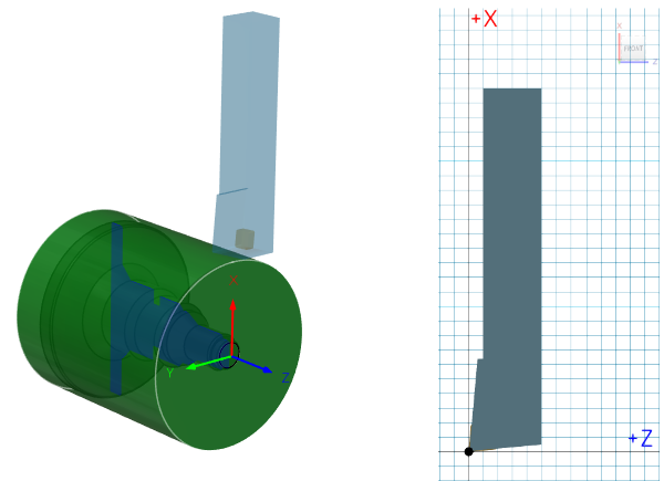
Setup defines the direction that the tool is pointing and the contact cutting point of the insert.

A turning tool on the canvas (left) and the 3D preview of the tool in the Tool Library (right).
| Parameter | Explanation |
|---|---|
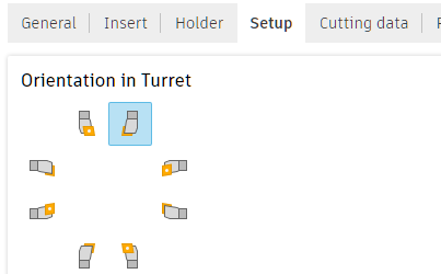
| Orientation | The angle of the tool with respect to the cutting direction. Select one of the 90-degree interval orientation options to orient the tool to match how the actual tool is oriented in the CNC machine. To set the orientation of the tool to an angle other than at a 90-degree interval, enter the custom angle in the Orientation box, then press Enter.  |
| Flip | Inverts the orientation of the tool. Note: This setting affects only the tool orientation and does not change the spindle direction. |
| Compensation | The toolpath compensation position. Select the Compensation point based on how you reference your tools at the CNC machine: Tip Tangent — Measured from each cutting edge, square to the axes. Tip — The intersection created along the insert cutting edges. Tip Center — The toolpath is referenced from the center of the tip. Insert Center — Used mostly for round or button shaped inserts.  |
| Clockwise Spindle Rotation | The direction of the spindle when the tool is in use. Clockwise is relative to the main spindle while looking down the chuck. Note: This setting changes only the spindle direction and does not affect the tool orientation. It is important to visually confirm simulation results and check the spindle M codes in the post-processed output before running code on a CNC machine. |
Cutting Data tab settings
Speed group
This section enables you to set default Spindle Speeds for the tool.
| Parameter | Explanation |
|---|---|
| Use Constant Surface Speed | When selected, the feed and speed is determined by the NC controller. CSS keeps a consistent amount of material moving past the tip of the tool based on the current cutting diameter. As the tool moves closer to the centerline of the part, the RPM increases. When deselected, the machine uses the programmed spindle speed and feedrate. |
| Spindle Speed | The rotational speed of the spindle when the Use Constant Surface Speed checkbox is deselected, given in Rotations Per/Min (RPM). Available for Turning Threading tool types. |
| Surface Speed | How fast the material moves across the tool tip, based on the current cutting diameter. Expressed in Ft/min for Inch mode and M/min for Metric mode. |
Feedrates group
| Parameter | Explanation |
|---|---|
| Use Feed per Revolution (FPR) | When selected, the feedrate is expressed as a Distance/Revolution (FPR). When deselected, the feedrate is expressed as a Distance/Time (Feed per minute or FPM). |
| Cutting Feedrate per Revolution | Feed used in cutting moves. |
| Lead-In Feedrate per Revolution | Feed used when leading in to a cutting move. |
| Lead-Out Feedrate per Revolution | Feed used when leading out from a cutting move. |
| Coolant | The type of coolant to use with the tool. Not all options are available for all NC machines. |
Post Processor tab settings
| Parameter | Explanation |
|---|---|
| Number | The number used to identify the tool in the NC program. |
| Break Control | When selected, enables you to check for tool breakage after use. This sends an output to the post that tells the machine to check for a broken tool. This is a machine-dependent function. |
| Comment | A text comment for the tool. The comment is typically output to the NC program. |
| Compensation Offset | The number used to identify the tool length offset and tool diameter offset in the NC program. |
| Manual Tool Change | When selected, forces a manual tool change. Deselect for machines with an automatic tool changer. |
| Turret | The turret position of the tool on the NC machine. |