Hole Recognition reference
This feature is part of an extension. Extensions are a flexible way to access additional capabilities in Fusion. Learn more.
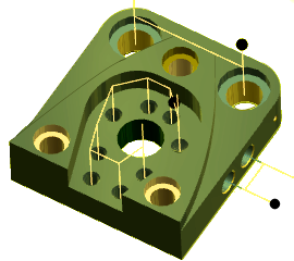
Hole Recognition automates the process to create hole machining operations.
Manufacture > Milling or Turning > Drilling > Hole Recognition ![]()
The model is analyzed for cylinders and those cylinders are assigned an Action. You can override the selection for a different type of Action. Actions will be some combination of Spot drilling, Drilling, Counter Boring, Boring, Tapping, or Reaming.
Tools will be selected from the tool libraries you specify. Standard Inch and Metric libraries are active by default, along with any tools in the current document. Select custom tool libraries that represent the tools you have available for a more focused tool selection.
Holes can be recognized in any plane, on any face, or limited to the plane of the currently active Setup. This makes Hole Recognition useful for any rotary application where holes intersect a cylinder (4th axis) or any multi faced part (5 axis).
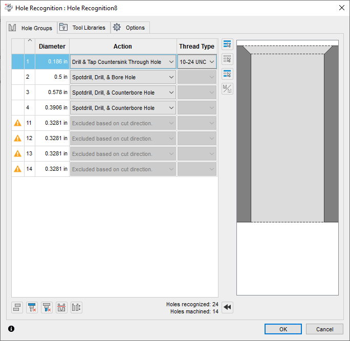
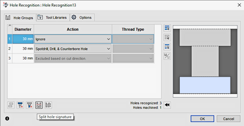
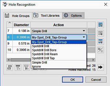
Hole Groups tab
Hole Groups create a list of hole features discovered on the model. Once all the diameters are sorted, Hole Recognition makes a list of Actions that can be performed on the holes, based on their size and features. Select any Diameter in the list and the matching holes are highlighted on the model.
If you right-click any of the columns, you can activate additional information.
Diameter
Displays the diameter of the holes in the group.
Action
Displays which types of operations can be performed to a hole size. Actions will be some combination of Spot drilling, Drilling, Counter Boring, Boring, Tapping, or Reaming. You may choose to Ignore the hole completely.
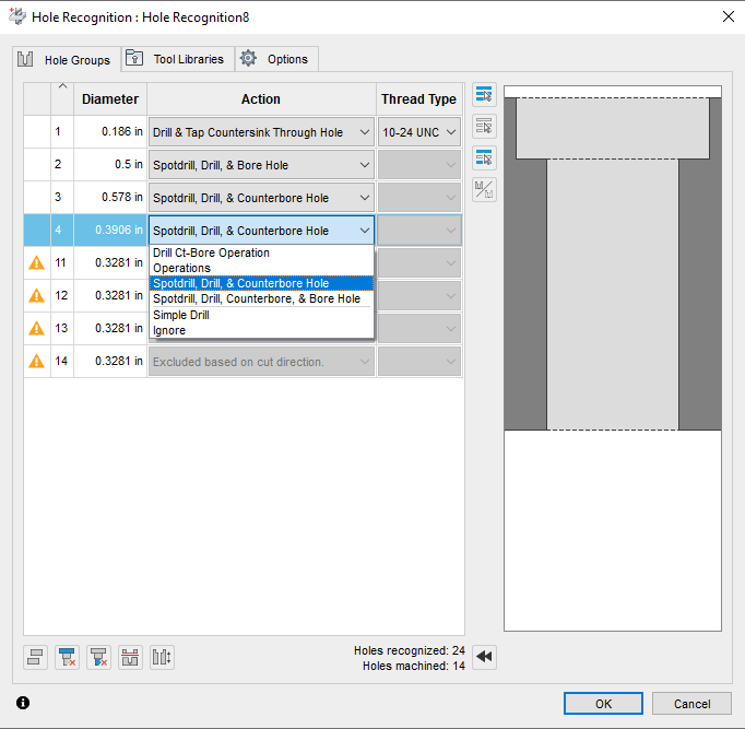
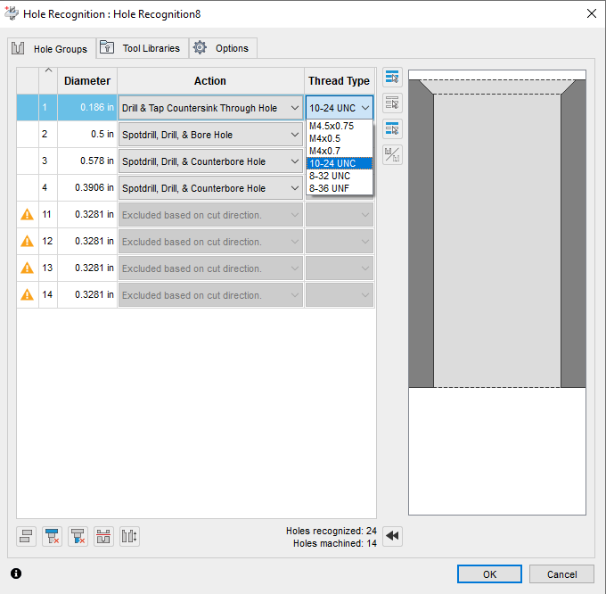
If you select an Action that requires Tapping, the Tread Type column offers options in a list.
Thread Type
Displays options available for threaded holes.
Group Modifiers
At the lower left of the dialog are the Modifiers. Use these to change the properties of the hole segments.
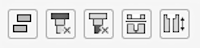
Left to right order:
- Explode Select Hole Groups - Makes each hole segment in the group, an individual group
- Delete Top Segment - Removes the top segment from a multi cylinder, concentric hole
- Delete Bottom Segment - Removes the bottom segment from a multi cylinder, concentric hole
- Split Hole Signature - Divides a through hole into two segments for machining from the opposite side
- Flip Hole - Changes the machining plane to the opposite side
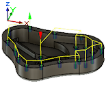
If the Multi-Axis Machining parameter on the Options tab is enabled, holes are viewed from any plane. For holes that require drilling from top and bottom planes, you can use these options to change how Fusion views the hole segments.
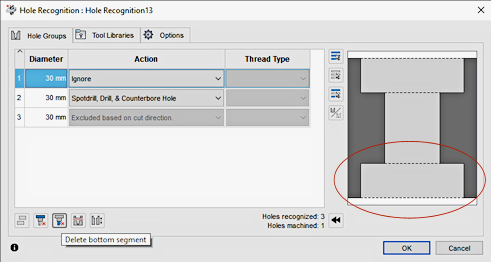
Removes the bottom segment of the hole so it can be machined from the top plane.
Splits the hole into two segments, so they can be machined separately from the top and the bottom planes. The blue area show, becomes a separate hole group.
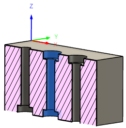
Unless special tools are used, the hole shown in blue needs to be machined from both the top and bottom.
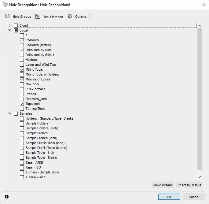
Tool Libraries tab
Tools are selected from the tool libraries that you specify. Standard Inch and Metric libraries from the Samples are active by default, along with any tools in the current document. Select custom Local tool libraries that represent the tools you have available for a more focused tool selection. If no matching tool exists in the selected libraries, the operation is created, but fails to generate until a tool is selected.
Tool Size - Currently the tool must match or be a smaller substitute than the hole size. If you have a hole of 0.187 IN diameter and your library only has a tool of 0.1875, no selection is made.
Counter Bored Holes - Currently Counter Bore hole operations are looking for Flat End mills to plunge the hole. Eventually other options will exist for Ct Boring, including circular milling options.
Properly equipped tool libraries are the key to successful Hole Recognition results.
Options tab
Holes can be recognized in any plane, on any face, or limited to the plane of the currently active Setup. This makes Hole Recognition useful for any rotary application where holes intersect a cylinder (4th axis) or any multi faced part (5 axis).
Multi-Axis Machining
Includes holes in all planes. By default, Fusion searches for holes in the current, active plane, where the Z axis represents the hole centerline.
Multi-Axis Machining selected.
Multi-Axis Machining deselected.
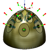
Find by Angle
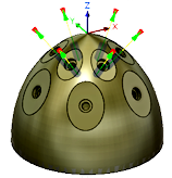
Sets a limiting angular range for selecting the holes to machine. Angles are set from the vertical spindle axis.
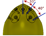
These holes range from 0 degrees to 70 degrees.
Minimum Angle and Maximum Angle
Sets a limiting range for selecting the holes to machine. Angles are set from the vertical spindle axis.
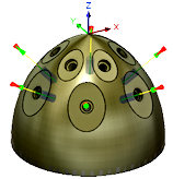
Minimum Angle of 0 degrees and Maximum Angle of 50 degrees.
Minimum Angle of 55 degrees and Maximum Angle of 70 degrees.
Find by Diameter
Sets a limiting range for selecting holes based on diameter.
Set the Maximum Diameter value for the holes to include.
Maximum Diameter
Sets a high limiting range for selecting holes based on diameter.
Organize Operations
Lets you choose to order by tool changes or hole size.
Minimize tool changes: If the same tool can be used on two different groups, those groups are output consecutively to reduce tool changes.
Group by size: If a hole requires multiple operations, all the operations are grouped.
Template Library Folder
Hole Recognition uses predefined Template Libraries to create the hole machining actions. By default, all available Template Libraries are considered for creating the hole operation. If you have custom templates, you can force Fusion to look only at operations from a specific library.
Click Select and pick the library to use.
Libraries can be stored in a Local or Cloud folder location.
Creating and using custom templates
It is possible to create custom examples of actions. Templates are multiple operations that are saved together as a group. If these operations fit with the holes discovered during the Hole Recognition process, they are shown in the Actions list.
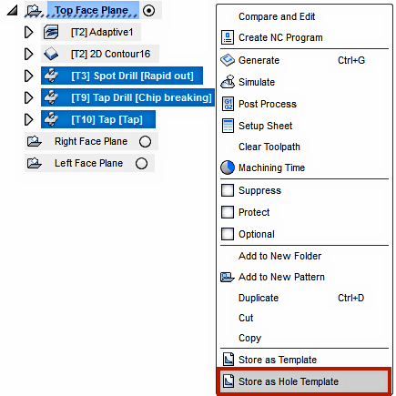
To create a custom template:
In the Browser, right-click the operations, and choose Store as Hole Template.
Give the template a meaningful name.
Select a Location.
Click Save.
The hole template appears in Template Library.
To adjust it, in the Manufacture workspace, on the toolbar, click Manage > Template Library.
Template Library dialog opens.
If the Hole Recognition process finds a feature that matches the characteristics of the Custom Template, it becomes available in the Action list.
Use Fewest Spot Drills Possible
Uses a single spot drill for all hole sizes.